Assembling the JG2 Terminal and Power Cable
Bacnground
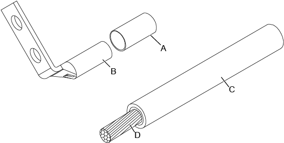
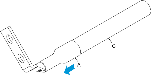
Figure 1 shows the components of a JG2 terminal and a power cable.
A. Heat shrink tubing |
B. JG2 terminal |
C. Insulation layer of a power cable |
D. Conductor of a power cable |
Procedure
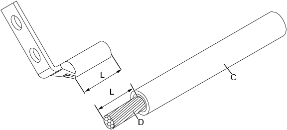
Strip a part of the insulation to expose the cable conductor with a length of L, as shown in Figure 2. The recommended values of L are listed in Table 1.

- When you strip a power cable, do not damage the conductor of the cable.
- If the bare crimping terminal is not provided by Huawei, you can adjust the value of L as required
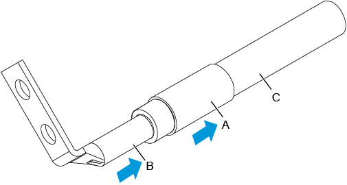
Put the heat shrink tubing onto the bare crimping terminal, as shown in Figure 3.
Put the bare crimping terminal onto the exposed conductor, and ensure that the bare crimping terminal is in good contact with the insulation of the power cable, as shown in Figure 3.
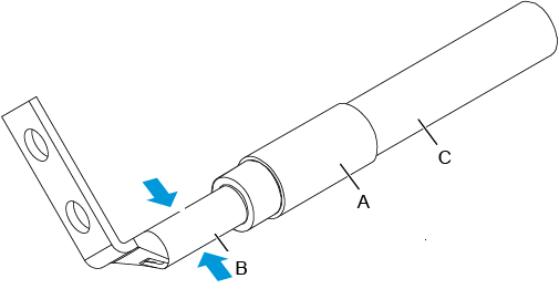
Crimp the joint parts of the bare crimping terminal and the conductor, as shown in Figure 4.
Push the heat shrink tubing toward the connector until the tube covers the crimped part, and then use a heat gun to heat the tube, as shown in Figure 5.
