Assembling the Shielded RJ45 Connector and Ethernet Cable
Background
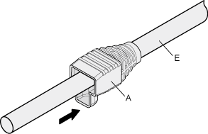
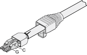
Figure 1 shows the components of an RJ45 connector and a shielded Ethernet cable.
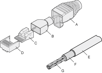
A. Jacket of connector |
B. Metal shell of connector |
C. Wire holder of connector |
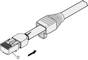
D. Plug of connector |
E. Jacket of Ethernet cable |
F. Shield layer of Ethernet cable |
G. Twisted-pair wires |
- |
Procedure
Fit the jacket of the connector onto the Ethernet cable, as shown in Figure 2.
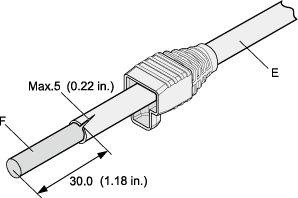
- Remove a 30 mm (1.18 in.) long section of the jacket, cut off the nylon twine inside the jacket, and cut a no more than 5 mm (0.20 in.) cleft in the jacket, as shown in Figure 3.

- When you remove a section of the jacket, do not damage the shield layer of the twisted-pair cable.
- When you remove the shield layer, do not damage the insulation of the twisted-pair cable.
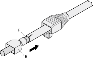
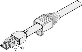
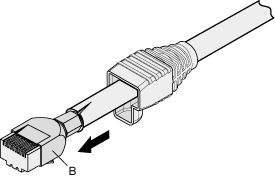
Fit the metal shell onto the twisted-pair cable. The shield layer is covered by the metal shell, as shown in Figure 4.
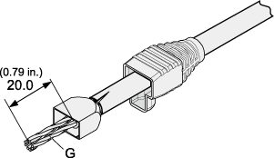
Fit the metal shell onto the twisted-pair cable until the shield layer is covered completely. Along the edge of the metal shell, cut off the aluminum foil shield layer and ensure that there is no surplus copper wire. The exposed twisted-pair cable is about 20 mm (0.79 in.) long, as shown in Figure 5.
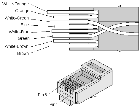
Lead the four pairs of twisted-pair wires through the wire holder, as shown in Figure 6 and Figure 7. Ensure that the colored wires are in the correct location in the cable.
Align the four pairs of cables in the holder, as shown in Figure 8. The connections between the wires and the pins are shown in Figure 9 and listed in Table 1.
Cut off the surplus cables along the lower edge of the wire holder, as shown in Figure 10.
- Put the connector body onto the wire holder and turn the metal shell by 90°, as shown in Figure 11.

Ensure that the wire holder is in good contact with the connector body.
Push the metal shell toward the connector body until the wire holder and the connector body are engaged completely. Crimp the connector, as shown in Figure 12.
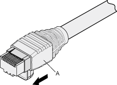
Push the jacket towards the metal shell until the metal shell is covered. This completes the assembly of one end of the cable, as shown in Figure 13.
To complete the assembly of the other end, repeat steps 1 to 10.