Assembling an Unshielded RJ45 Connector and Ethernet Cable
Background
Figure 1 shows the components of an unshielded RJ45 connector and cable.
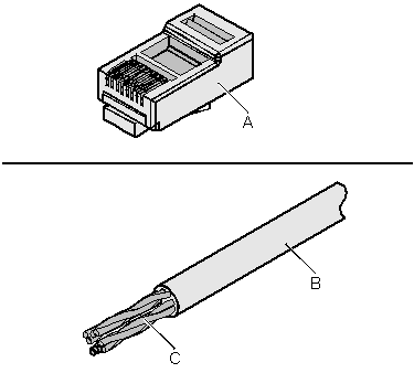
A. Plug of connector |
B. Jacket |
C. Twisted-pair wires |
Procedure
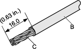
- Remove a 16-mm (0.63 in.) long section of the jacket, as shown in Figure 2.

When you remove the shield layer, do not damage the insulation of the twisted-pair cable.
- Align the four pairs of wires and cut the ends neatly, as shown in Figure 3. The connections between the wires and the pins are listed in Table 1.
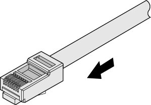
- Feed the cable into the plug, and crimp the connector, as shown in Figure 4.

When inserting the cable, check from the side or bore of the plug to ensure that the cable is completely seated in the plug.
- To complete the assembly of the other end, repeat steps 1 to 3.