Installing Power Cables in a Dual-DC Connector
This section describes how to install power cables in a dual-DC connector.
Context

Colors and structures of cables vary in different countries or regions. If cables are purchased locally, they must comply with local rules and regulations.
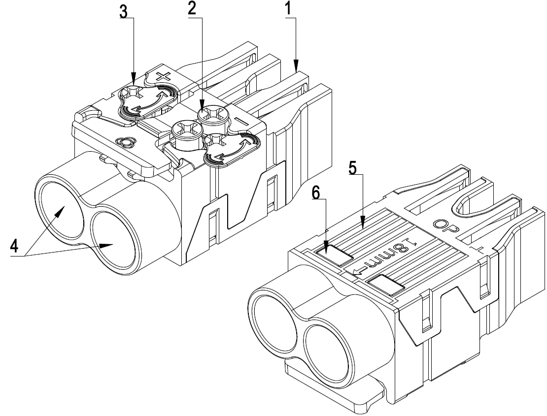
Figure 1 shows the components of a dual-DC connector.
(1) Connector body |
(2) Screw |
(3) Cover plate |
(4) Wiring hole |
(5) Scale |
(6) Viewing window |
Procedure
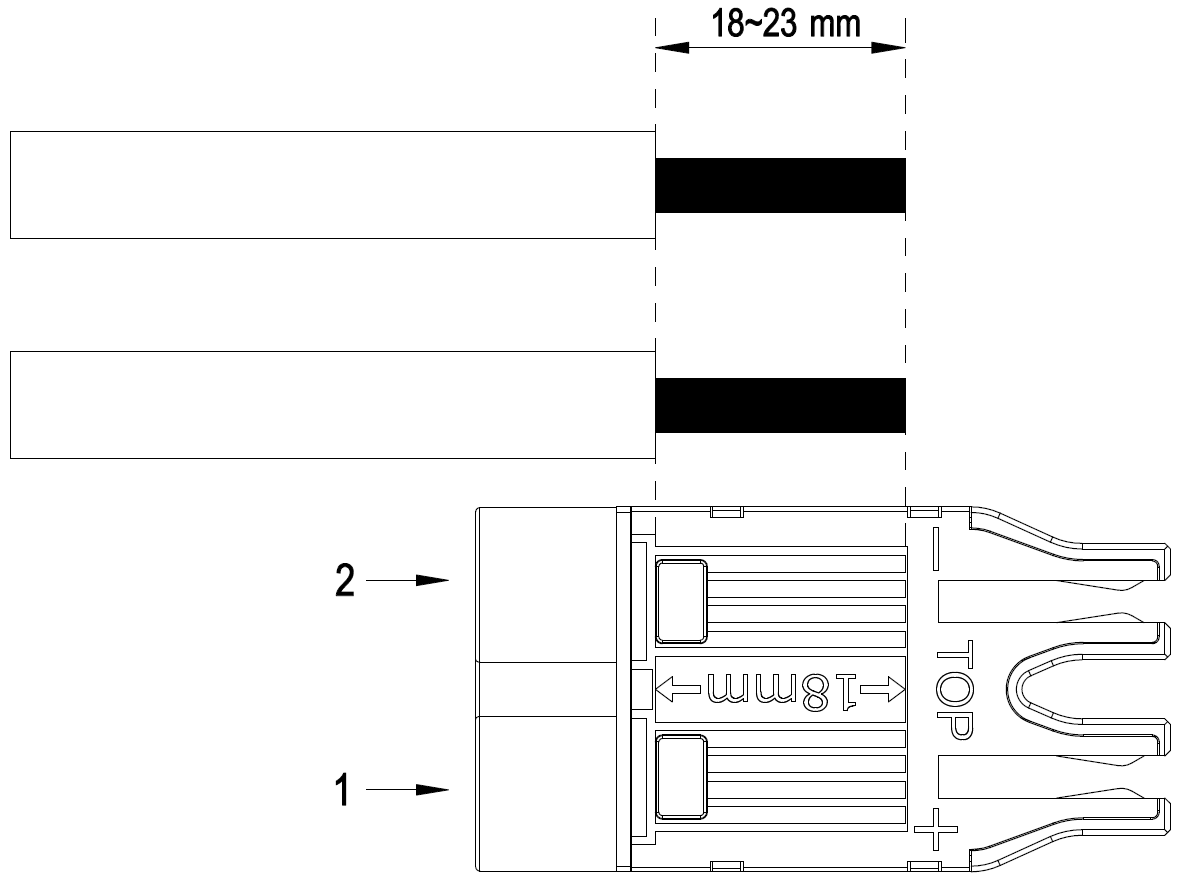
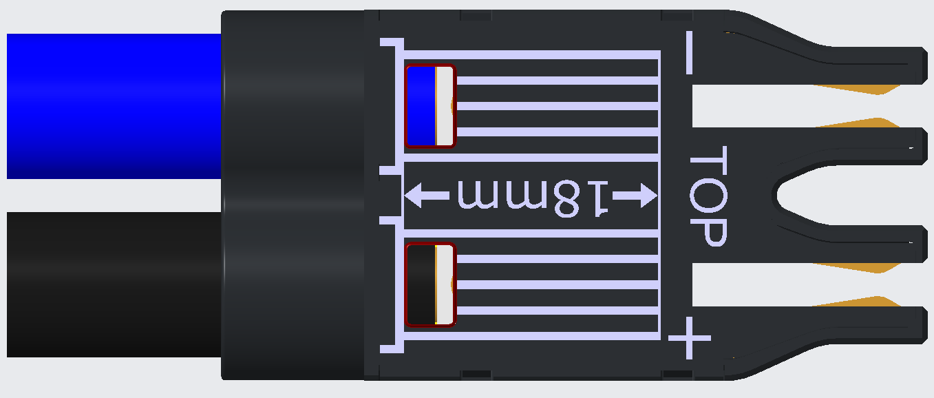
- Trim power cables according to the scale on the connector, as shown in Figure 2.

- Strip 18–23 mm off the outer jacket from the end.
- Ensure that the wires do not split during cable stripping.

Cables applicable to dual-DC connectors shall have a cross-sectional area of 16–25 mm2.
- Rotate the cover plate until the screws are completely exposed, as shown in the following figure.
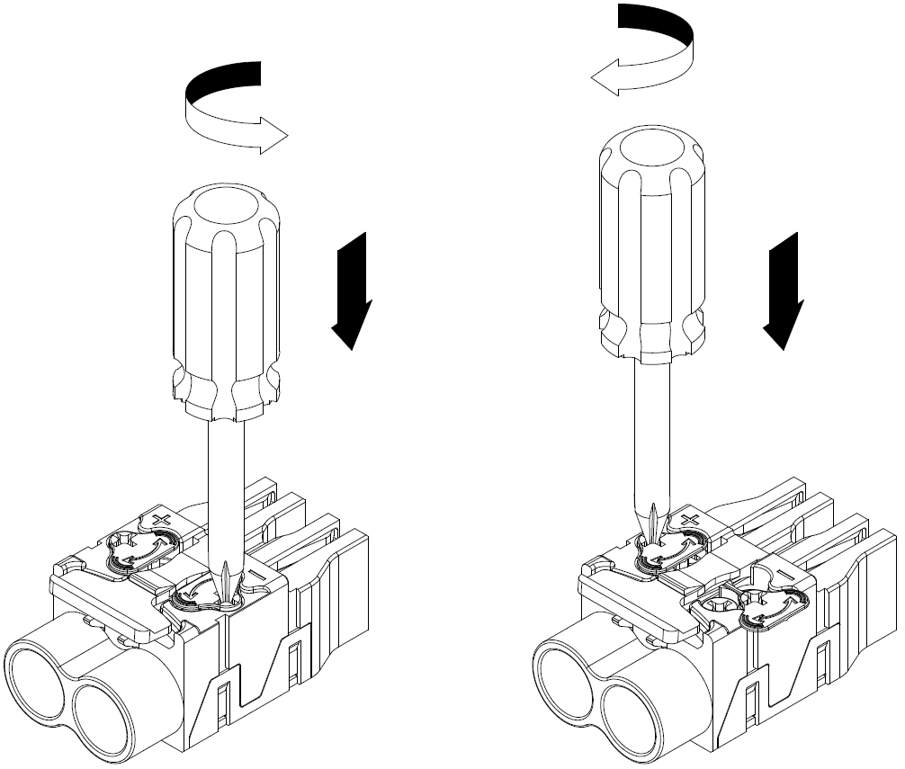
- Loosen the screws to open the crimping plate.
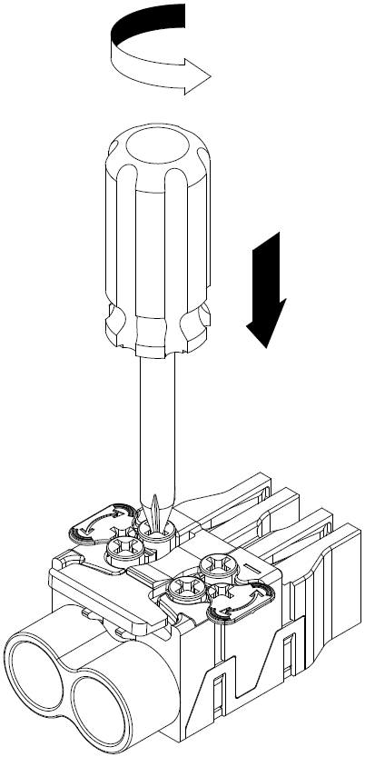
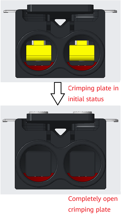
- Insert the positive wire into hole (+) and the negative wire into hole (–). After the wires are properly inserted, secure them by tightening the screws.
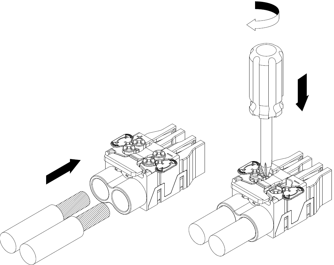

- Ensure that positive and negative wires are inserted into correct holes. Otherwise, device malfunctions or personal injury can easily occur. Before powering on the device, carefully check the polarities of power cables.
- Remove the connector from the device before inserting wires. This is because inserting wires into a connector when the connector is still on the device can cause serious consequences, such as sparking, fuse blowout, and connector damage.
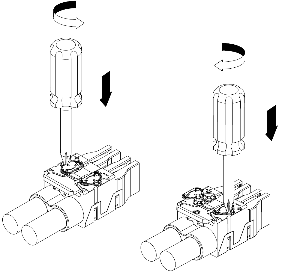
- After wires are inserted into the correct holes, use a Phillips screwdriver with PH2 (φ5) head size to secure the wires with a torque of 1.6–1.9 N m.
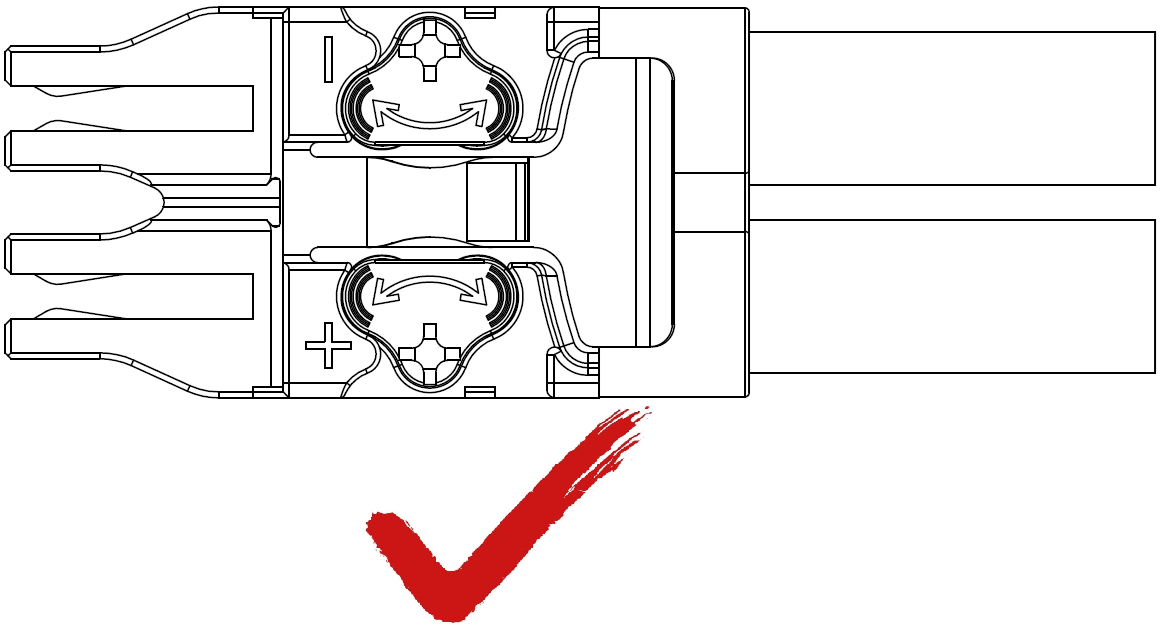
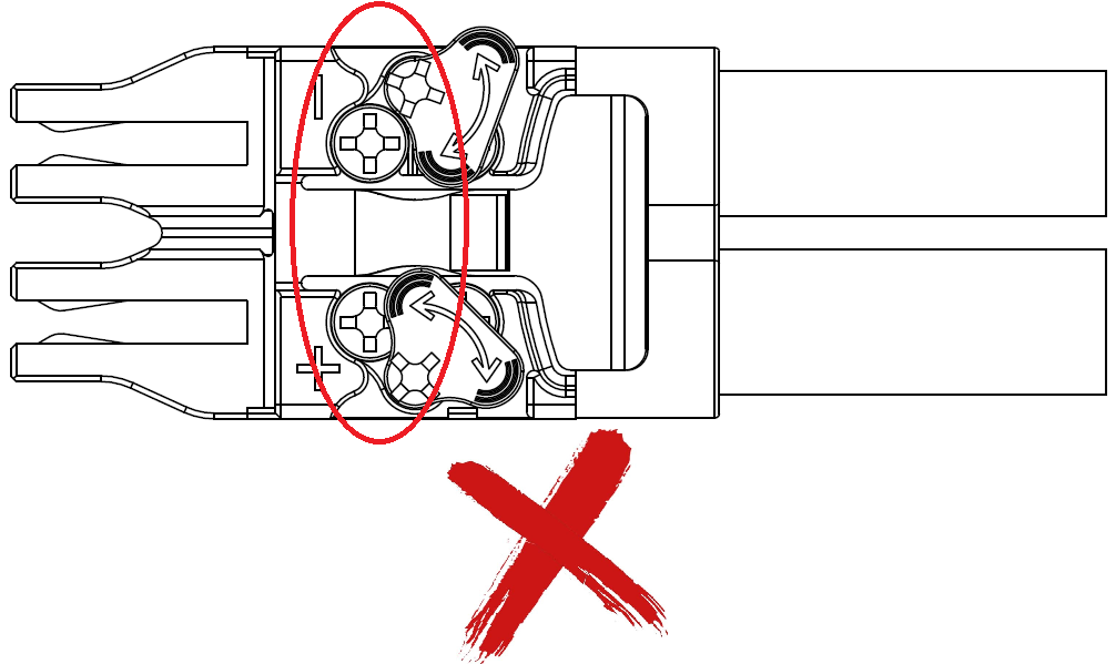
- Rotate the cover plate to completely cover the screws.Figure 3 Rotating the cover plate
- Check whether cable installation is qualified.

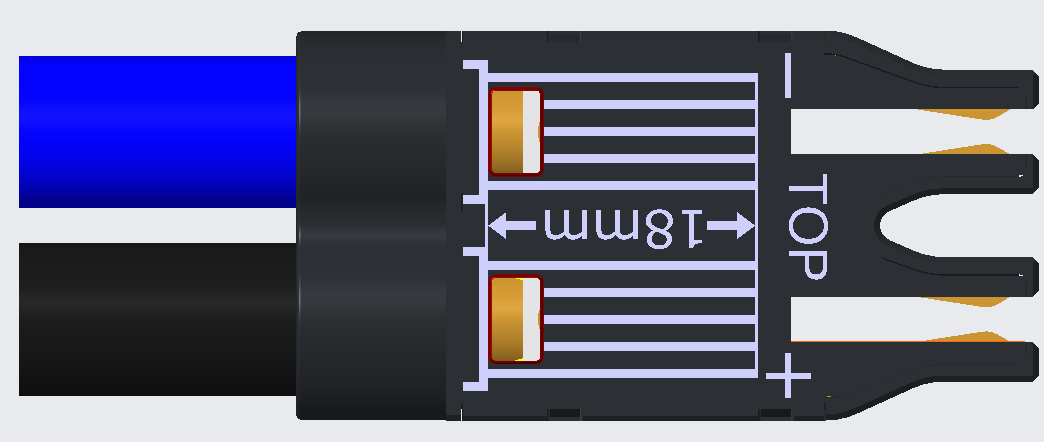
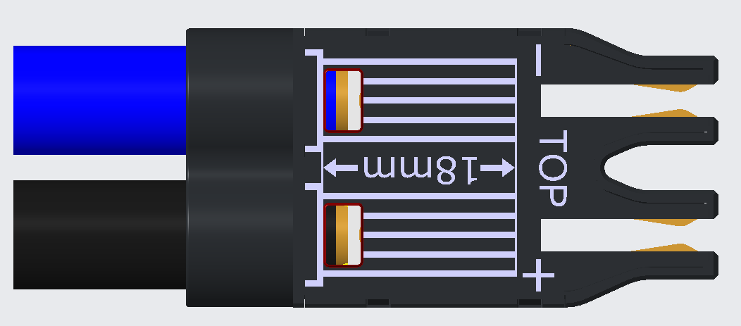
- Power wires must be properly installed, as shown in Figure 4. If you can see the internal copper wires when pulling the power cable, the installation is unqualified, as shown in Figure 5.
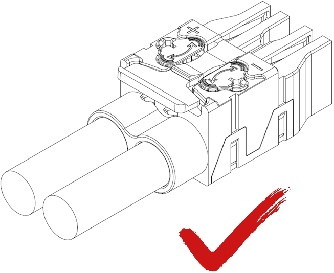
- After tightening the screws, ensure that the cover plate is rotated to the required position to completely cover the screws, as shown in Figure 6. Otherwise, the screws are still exposed to some extent, as shown in Figure 7.
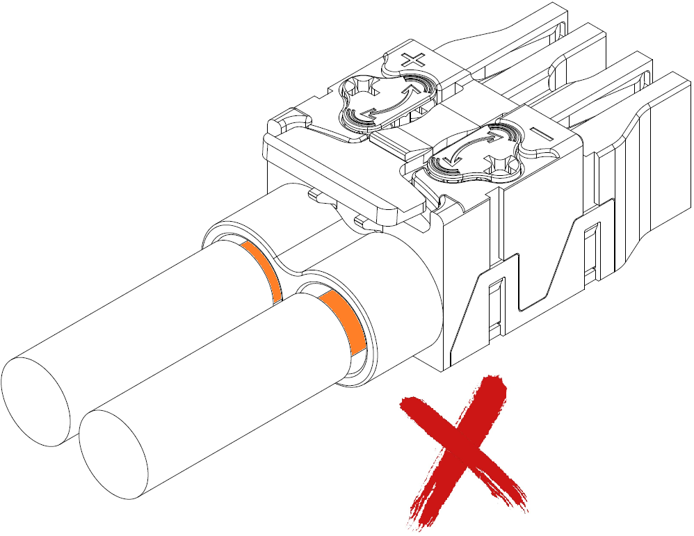
- You can check whether the copper wires have been tightly crimped via the viewing window, as shown in Figure 8. If the outer jacket of the cable can be seen via the viewing window, the cable installation is unqualified, as shown in Figure 9 and Figure 10.
