Assembling the Cord End Terminal and Power Cable

Background

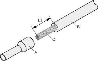
Figure 1 shows the components of a cord end terminal and a power cable.

Figure 1 Components of a cord end terminal and a power cable

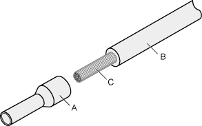
A. Cord end terminal

B. Insulation layer of a power cable

C. Conductor of a power cable

Procedure

  1. Strip a part of the insulation layer to expose the cable conductor with a length of L1, as shown in Figure 2. Determine the value of L1 based on the cross-sectional area of the cable conductor. The recommended values of L1 are listed in Table 1.

    When you strip a power cable, do not damage the conductor of the cable.

    Figure 2 Stripping a power cable (cord end terminal)
    Table 1 Mapping between the cross-sectional area of the conductor and the value of L1

    Cross-Sectional Area of Conductor (mm2 (in.2))

    Value of L1 (mm (in.))

    Cross-Sectional Area of Conductor (mm2 (in.2))

    Value of L1 (mm (in.))

    1

    8

    10

    15

    1.5

    10

    16

    15

    2.5

    10

    25

    18

    4

    12

    35

    19

    6

    14

    50

    26

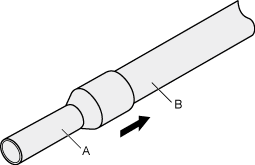
  2. Put the cord end terminal onto the exposed conductor and ensure that the conductor is aligned with the edge of the cord end terminal, as shown in Figure 3.

    After the conductor is fed into the cord end terminal, the protruding part of the conductor must not be longer than 1 mm (0.04 in.).

    Figure 3 Putting the cord end terminal onto the conductor
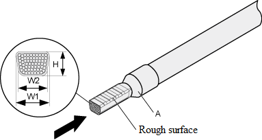
  3. Select a proper cross-sectional area, and crimp the joint parts of the cord end terminal and the conductor, as shown in Figure 4.
    Figure 4 Crimping the joint parts of the cord end terminal and the conductor
  4. Check the maximum width of the crimped terminal. Table 2 lists the maximum width of a crimped terminal.
    Table 2 Maximum width of a crimped terminal

    Cross-Sectional Area of the Terminal (mm2)

    Maximum Width of the Crimped Terminal — W1 (mm(in.))

    0.25

    1

    0.5

    1

    1.0

    1.5

    1.5

    1.5

    2.5

    2.4

    4

    3.1

    6

    4

    10

    5.3

    16

    6

    25

    8.7

    35

    10

Copyright © Huawei Technologies Co., Ltd.
< Previous topic Next topic >