Example for Configuring the Multicast MAC Encapsulation Mode for 1588v2 Packets to Implement Network-wide Clock Synchronization
1588v2 is used to transmit frequency signals and time signals from the BITS server, allowing network-wide clock synchronization on the wireless transport network and wireless access network. NetEngine 8000 Fs by default use the multicast MAC encapsulation mode to transmit 1588v2 packets. For NodeBs that support multicast MAC encapsulation of 1588v2 packets, it is convenient to implement network-wide clock synchronization by configuring all NetEngine 8000 Fs as BCs.
Context
Networking Requirements
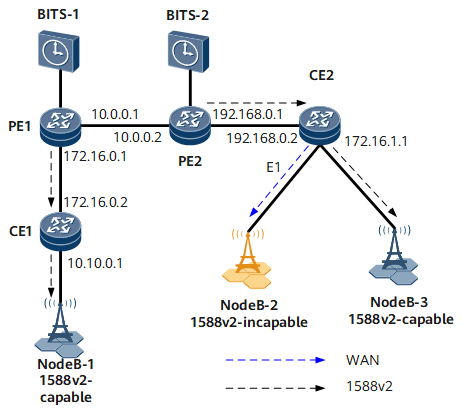
On the network shown in Figure 1, the transport network transmits wireless services between NodeBs, and all transport network nodes support 1588v2. Core nodes PE1 and PE2 receive time information from the BITS server. NodeB-2 supports SyncE, instead of 1588v2. Both NodeB-1 and NodeB-3 support 1588v2. PE1 and PE2 dynamically select the grandmaster clock. The grandmaster clock transmits 1588v2 time signals over the entire network. Frequency synchronization can be achieved between NodeBs and transport network devices. Time synchronization can be achieved between 1588v2-capable NodeBs and transport network devices.
Because all nodes on the transport network support 1588v2, they can be configured as BCs to transmit clock information. For NodeB-2 that does not support 1588v2, frequency information can be transmitted through the clock signals over an E1 line.

The configurations in this example are performed on PE1, PE2, CE1, and CE2. HUAWEI NetEngine 8000 F Series can function as PE1, PE2, CE1.
Device Name |
Interface Name |
Interface IP Address |
|---|---|---|
PE1 |
GE 0/1/8 |
10.0.0.1/24 |
PE1 |
GE 0/1/0 |
172.16.0.1/24 |
PE2 |
GE 0/1/8 |
10.0.0.2/24 |
PE2 |
GE 0/1/0 |
192.168.0.1/24 |
CE1 |
GE 0/1/8 |
172.16.0.2/24 |
CE1 |
GE 0/1/0 |
10.10.0.1/24 |
CE2 |
GE 0/1/0 |
192.168.0.2/24 |
CE2 |
GE 0/1/1 |
172.16.1.1/24 |
NodeB-1 |
- |
10.10.0.2/24 |
NodeB-3 |
- |
172.16.1.2/24 |
Configuration Roadmap
The configuration roadmap is as follows:
Connect PE1 and PE2 to BITS servers.
Configure PE1, PE2, CE1, and CE2 as BCs.
Configure devices to use the default multicast MAC encapsulation mode to transmit 1588v2 packets.
Data Preparation
To complete the configuration, you need the following data:
Delay measurement mechanism of 1588 links: PDelay
Value of the 1588v2 clock domain where clock devices reside
Interval at which Announce messages are sent and the number of times Announce message receiving times out
Interval at which Sync messages are sent
Interval at which PDelay messages are sent
Procedure
- Assign an IP address to each interface and configure OSPF. The configuration details are not provided here.
- Configure PE1 and PE2 to use clock interfaces to import BITS signals.
- Configure PE1, PE2, CE1, and CE2 as BCs.
- Verify the configuration.
After completing the configurations, run the display ptp all state command to view the 1588v2 operating status. The following example uses the command output on CE1. The command output shows that GE 0/1/8 of CE1 is working in the Slave state, the grandmaster clock ID is 000a0bfffe0c0dd4, and the parent clock ID is also 000a0bfffe0c0dd4. CE1 has synchronized with the master clock source.
<CE1> display ptp all
  Device config info
  ------------------------------------------------------------------
  PTP state         :enabled    Domain  value      :1
  Slave only        :no         Device type        :BC
  Set port state    :no         Local clock ID     :000a0bfffe0c0d42
  Acl               :no         Virtual clock ID   :no
  Acr               :no         Time lock success  :yes
  Asymmetry measure :disable    Passive measure    :disable

  BMC run info
  ------------------------------------------------------------------
  Grand clock ID    :000a0bfffe0c0dd4
  Receive number    :GigabitEthernet0/1/8
  Parent clock ID   :000a0bfffe0c0dd4
  Parent portnumber :6417
  Priority1         :128        Priority2          :128
  Step removed      :1          Clock accuracy     :49
  Clock class       :187        Time Source        :160
  UTC Offset        :0          UTC Offset Valid   :False
  Timescale         :ARB        Time Traceable     :False
  Leap              :None       Frequence Traceable:False
  Offset scaled     :0xffff     Sync uncertain     :False

  Port info
  Name                  State        Delay-mech Ann-timeout Type Domain
  ------------------------------------------------------------------------
  GigabitEthernet0/1/8  slave        pdelay      10          BC   1
  Time Performance Statistics(ns): Slot X  Card X  Port X
  ------------------------------------------------------------------------
  Realtime(T2-T1)   :534               Pathdelay     :0
  Max(T2-T1)        :887704804
  Min(T2-T1)        :512

  Clock source info
  Clock Pri1 Pri2 Accuracy Class TimeSrc Signal Switch Direction In-Status
  ------------------------------------------------------------------------
  local 200  128  0x31     187   0xa0     -      -      -         -
  bits1 128  128  0x20       6   0x20     none   off   -/-        abnormal
Configuration Files
CE1 configuration file
#
 sysname CE1
#
 ptp enable
 ptp device-type bc
 ptp domain 1
#
interface GigabitEthernet0/1/8
 undo shutdown
 ip address 172.16.0.2 255.255.255.0
 ptp enable
 ptp delay-mechanism pdelay
#
interface GigabitEthernet0/1/0
 undo shutdown
 ip address 10.10.0.1 255.255.255.0
 ptp enable
 ptp delay-mechanism pdelay
#
 ospf 1
 area 0.0.0.0
 network 172.16.0.0 0.0.0.255
 network 10.10.0.0 0.0.0.255
#
CE2 configuration file
#
 sysname CE2
#
 ptp enable
 ptp device-type bc
 ptp domain 1

#
interface GigabitEthernet0/1/0
 undo shutdown
 ip address 192.168.0.2 255.255.255.0
 ptp enable
 ptp delay-mechanism pdelay
#
interface GigabitEthernet0/1/1
 undo shutdown
 ip address 172.16.1.1 255.255.255.0
 ptp enable
 ptp delay-mechanism pdelay
#
 ospf 1
 area 0.0.0.0
 network 192.168.0.0 0.0.0.255
 network 172.16.1.0 0.0.0.255
#
PE1 configuration file
#
 sysname PE1
#
 ptp enable
 clock bits-type bits1 1pps input
 ptp clock-source bits1 on
 ptp clock-source bits1 priority1 2
 ptp device-type bc
 ptp domain 1
interface GigabitEthernet0/1/0
 undo shutdown
 ip address 172.16.0.1 255.255.255.0
 ptp enable
 ptp delay-mechanism pdelay
interface GigabitEthernet0/1/8
 undo shutdown
 ip address 10.0.0.1 255.255.255.0
 ptp enable
 ptp delay-mechanism pdelay
#
 ospf 1
 area 0.0.0.0
 network 10.0.0.0 0.0.0.255
 network 172.16.0.0 0.0.0.255
#
PE2 configuration file
#
 sysname PE2
#
 ptp enable
 clock bits-type bits1 1pps input
 ptp clock-source bits1 on
 ptp clock-source bits1 priority1 1
 ptp device-type bc
 ptp domain 1
interface GigabitEthernet0/1/0
 undo shutdown
 ip address 192.168.0.1 255.255.255.0
 ptp enable
 ptp delay-mechanism pdelay
interface gigabitethernet 0/1/8
 undo shutdown
 ip address 10.0.0.1 255.255.255.0
 ptp enable
 ptp delay-mechanism pdelay
#
 ospf 1
 area 0.0.0.0
 network 10.0.0.0 0.0.0.255
 network 192.168.0.0 0.0.0.255
#