Example for Configuring RUI with Automatic Route Advertisement
This section describes an example for configuring RUI with automatic route advertisement.
Networking Requirements
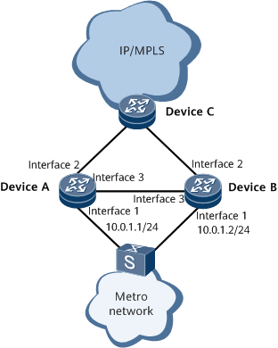
In Figure 1, users access Device A and Device B through a LAN switch. The two devices run VRRP to determine the master and backup status. Basic user access functions are configured on Device A and Device B, allowing the users to go online through the master device.
Automatic route advertisement is easier to configure than manual route advertisement. Automatic route advertisement prevents the problem where if a fault in a BRAS occurs after a master/slave BRAS switchover is implemented, UNRs cannot be automatically advertised after the BRAS recovers. The default route cost can be used to control route preference. If dual-system hot backup is configured on BRASs, a routing protocol imports UNRs and trusts UNR preference values. This allows the network segment route of the primary address pool to have higher route precedence than that of the secondary address pool.
To improve link utilization, allow a VRRP group to transmit user packets with odd MAC addresses and another VRRP group to transmit user packets with even MAC addresses to load-balance user packets between Device A and Device B.

Interfaces 1 through 3 in this example represent GE 0/1/0, GE 0/1/8 and GE 0/1/16 respectively.
Device |
Interface |
IP Address |
DeviceA |
GE0/1/0 |
10.0.1.1/24 |
DeviceA |
GE0/1/8 |
10.0.0.1/24 |
DeviceA |
GE0/1/16 |
10.1.1.6/24 |
DeviceA |
Loopback0 |
1.1.1.1/32 |
DeviceA |
Loopback1 |
22.22.22.22/32 |
DeviceB |
GE0/1/0 |
10.0.1.2/24 |
DeviceB |
GE0/1/8 |
10.0.2.1/24 |
DeviceB |
GE0/1/16 |
10.1.1.7/24 |
DeviceB |
Loopback0 |
2.2.2.2/32 |
DeviceB |
Loopback1 |
88.88.88.88/32 |
Configuration Roadmap
The configuration roadmap is as follows:
Configure basic user access functions and ensure that the two devices have the same configuration. For details, see HUAWEI NetEngine 8000 F SeriesRouter Guide - User Access.
Establish a dual-device backup platform.
Set NAS parameters and a traffic backup interval (or traffic threshold).
Configure a protection path for returned network-side traffic.
Bind an RBP to an interface from which users go online.
Enable a routing protocol to trust UNR cost values.
Data Preparation
To complete the configuration, you need the following data:
VRRP ID
Interface IP addresses of routers that back up each other
Backup ID, which is used together with an RBS to determine the RBP to which the user belongs
Procedure
- Establish a dual-device backup platform. The configuration on Device A is used as an example. The configuration on Device B is similar to that on Device A.
In this example, only RUI-related configuration is described.
# Configure BFD sessions named bfd and bfd2 at the access side to rapidly detect faults in interfaces or links of two VRRP groups and trigger a master/backup VRRP switchover if a fault occurs. Set the peer IP addresses for BFD sessions to 10.0.1.2 (IP address of Device B's GE 0/1/0.2) and 10.0.0.2 (IP address of Device B's GE 0/1/0.3).
[~DeviceA] bfd
[*DeviceA-bfd] quit
[*DeviceA] bfd bfd bind peer-ip 10.0.1.2
[*DeviceA-bfd-session-bfd] discriminator local 1
[*DeviceA-bfd-session-bfd] discriminator remote 2
[*DeviceA-bfd-session-bfd] commit
[~DeviceA-bfd-session-bfd] quit
[~DeviceA] bfd bfd2 bind peer-ip 10.0.0.2
[*DeviceA-bfd-session-bfd2] discriminator local 3
[*DeviceA-bfd-session-bfd2] discriminator remote 4
[*DeviceA-bfd-session-bfd2] commit
[~DeviceA-bfd-session-bfd2] quit
# Configure a VRRP group on GE 0/1/0.2 and another one on GE 0/1/0.3, and enable each VRRP group to track a specific BFD session and the network-side interface status.
[~DeviceA] interface gigabitethernet 0/1/0.2
[*DeviceA-GigabitEthernet0/1/0.2] vlan-type dot1q 200
[*DeviceA-GigabitEthernet0/1/0.2] ip address 10.0.1.1 255.255.255.0
[*DeviceA-GigabitEthernet0/1/0.2] vrrp vrid 1 virtual-ip 10.0.1.100
[*DeviceA-GigabitEthernet0/1/0.2] admin-vrrp vrid 1
[*DeviceA-GigabitEthernet0/1/0.2] vrrp vrid 1 priority 120
[*DeviceA-GigabitEthernet0/1/0.2] vrrp vrid 1 track bfd-session 1 peer
[*DeviceA-GigabitEthernet0/1/0.2] vrrp vrid 1 track interface gigabitethernet 0/1/8 reduced 50
[*DeviceA-GigabitEthernet0/1/0.2] commit
[~DeviceA-GigabitEthernet0/1/0.2] quit
[~DeviceA] interface gigabitethernet 0/1/0.3
[*DeviceA-GigabitEthernet0/1/0.3] vlan-type dot1q 201
[*DeviceA-GigabitEthernet0/1/0.3] ip address 10.10.0.1 255.255.255.0
[*DeviceA-GigabitEthernet0/1/0.3] vrrp vrid 2 virtual-ip 10.0.0.100
[*DeviceA-GigabitEthernet0/1/0.3] admin-vrrp vrid 2
[*DeviceA-GigabitEthernet0/1/0.3] vrrp vrid 2 priority 100
[*DeviceA-GigabitEthernet0/1/0.3] vrrp vrid 2 preempt-mode timer delay 600
[*DeviceA-GigabitEthernet0/1/0.3] vrrp vrid 2 track bfd-session 3 peer
[*DeviceA-GigabitEthernet0/1/0.3] vrrp vrid 2 track interface gigabitethernet 0/1/8 reduced 50
[*DeviceA-GigabitEthernet0/1/0.3] vrrp recover-delay 20
[*DeviceA-GigabitEthernet0/1/0.3] commit
[~DeviceA-GigabitEthernet0/1/0.3] quit
Different priorities must be configured for devices in a VRRP group. The device with a higher priority functions as the master device.
# Configure an RBS.
[~DeviceA] remote-backup-service service1
[*DeviceA-rm-backup-srv-service1] peer 88.88.88.88 source 22.22.22.22 port 2046
[*DeviceA-rm-backup-srv-service1] track interface gigabitethernet 0/1/8
[*DeviceA-rm-backup-srv-service1] commit
You can run the track bfd-session command in the RBS view to track the peer BFD sessions established on the network side of the master and backup devices, achieving rapid peer status detection. For configuration details, see the corresponding command reference.
# Configure an RBP.
[~DeviceA] remote-backup-profile profile1
[*DeviceA-rm-backup-prf-profile1] peer-backup hot
[*DeviceA-rm-backup-prf-profile1] vrrp-id 1 interface gigabitethernet 0/1/0.2 even-mac
[*DeviceA-rm-backup-prf-profile1] vrrp-id 2 interface gigabitethernet 0/1/0.3 odd-mac
[*DeviceA-rm-backup-prf-profile1] backup-id 10 remote-backup-service service1
[*DeviceA-rm-backup-prf-profile1] service-type bras
[*DeviceA-rm-backup-prf-profile1] quit
[*DeviceA] remote-backup-profile profile2
[*DeviceA-rm-backup-prf-profile2] peer-backup hot
[*DeviceA-rm-backup-prf-profile2] vrrp-id 1 interface gigabitethernet 0/1/0.2
[*DeviceA-rm-backup-prf-profile2] backup-id 10 remote-backup-service service1
[*DeviceA-rm-backup-prf-profile2] service-type bras
[*DeviceA-rm-backup-prf-profile2] commit
[~DeviceA-rm-backup-prf-profile2] quit
- Set NAS parameters and a traffic backup interval. The configuration on Device A is used as an example. The configuration on Device B is similar to that on Device A.
# Set NAS parameters.
[~DeviceA] remote-backup-profile profile1
[*DeviceA-rm-backup-prf-profile1] nas logic-ip 1.2.3.4
[*DeviceA-rm-backup-prf-profile1] nas logic-port gigabitethernet 0/1/0
[*DeviceA-rm-backup-prf-profile1] nas logic-sysname huawei
[*DeviceA-rm-backup-prf-profile1] commit
# Set a traffic backup interval.
[~DeviceA] remote-backup-profile profile1
[*DeviceA-rm-backup-prf-profile1] traffic backup interval 10
[*DeviceA-rm-backup-prf-profile1] commit
- Bind pool1 configured in the AAA domain to the RBS and configure a protection path for returned network-side traffic. The configuration on Device A is used as an example. The configuration on Device B is similar to that on Device A.
[~DeviceA] remote-backup-service service1
[*DeviceA-rm-backup-srv-service1] ip-pool pool1
[*DeviceA-rm-backup-srv-service1] protect redirect ip-nexthop 10.1.1.7 interface gigabitethernet 0/1/16
[*DeviceA-rm-backup-srv-profile1] commit
- Bind the RBP to GE 0/1/0.1 through which users go online. The configuration on Device A is used as an example. The configuration on Device B is similar to that on Device A.
[~DeviceA] interface gigabitethernet 0/1/0.1
[*DeviceA-GigabitEthernet0/1/0.1] remote-backup-profile profile1
[*DeviceA-GigabitEthernet0/1/0.1] commit
[~DeviceA-GigabitEthernet0/1/0.1] quit
- Enable each router to use the default cost values of imported routes to control address pool route priorities.
[~DeviceA] peer-backup route-cost auto-advertising
[*DeviceA] commit
Perform one of the following steps based on the type of routing protocol:- Run the import-route unr inherit-cost command in the IS-IS view.
- Run the following commands in the OSPF view:
- default cost inherit-metric
- import-route unr
- Run the import-route unr command in the BGP view.
- Verify the configuration.
After successfully configuring the RBP, run the display remote-backup-profile command. According to the command output, the RBS type is bras, the RBP named profile1 is bound to GigabitEthernet 0/1/0.1 from which users go online, and Device A is in the Master state.
<DeviceA> display remote-backup-profile profile1
-----------------------------------------------
 Profile-Index        : 0x802
 Profile-Name         : profile1
 Service              : bras
 Remote-backup-service: service1
 Backup-ID            : 10
 track protocol       : VRRP
 VRRP-ID              : 1
 VRRP-Interface       : GigabitEthernet0/1/0.2
 Access-Control       : Even-Mac
 State                : Master
 Peer-state           : Slave
 VRRP-ID              : 2
 VRRP-Interface       : GigabitEthernet0/1/0.3
 Access-Control       : Odd-Mac
 State                : Slave
 Peer-state           : Master
 Interface            :
                        GigabitEthernet0/1/0.1
 Backup mode          : hot
 Slot-Number          : 1
 Card-Number          : 0
 Port-Number          : 0
 Nas logic-port       : Gigabitethernet 0/1/0
 Nas logic-ip         : 1.2.3.4
 Nas logic-sysname    : huawei
 Traffic interval     : 10(minutes)
After the RBS is configured successfully, the TCP connection status becomes Connected.
<DeviceA> display remote-backup-service service1
----------------------------------------------------------
 Service-Index    : 0
 Service-Name     : service1
 TCP-State        : Connected
 Peer-ip          : 88.88.88.88
 Source-ip        : 22.22.22.22
 TCP-Port         : 2046
 Track-BFD        : --
 Track-interface0 : GigabitEthernet0/1/8
 Track-interface1 : --
----------------------------------------------------------

 IP Pool:
         pool1
ip pool:
         poolv4_yyz metric 10
         r3 metric 10
         r4 metric 20
         remotev4 metric 10
ipv6 pool:
         1234 metric 10
         iana_yyz metric 10
         iapd_yyz metric 10
         lo metric 10
         loc_vpn metric 10
         nd metric 10
         pd metric 10
         remote_del_yyz metric 10
         remotev6_yyz metric 10
 Failure ratio    : 100%
 Failure duration : 0 min
NAT instance : nat1
 ----------------------------------------------------------
 Rbs-ID         : 0
 Protect-type   : ip-redirect
 Next-hop       : 10.1.1.7
 Vlanid         : 0
 Peer-ip        : 10.1.1.7
 Vrfid          : 0
 Tunnel-index   : 0x0
 Tunnel-state   : UP
 Tunnel-OperFlag: NORMAL
 Spec-interface : GigabitEthernet0/1/16
 Out-interface  : GigabitEthernet0/1/16
 User-number    : 0
After users go online, you can view the information about backup users. The information includes the number of locally logged-in users and the number of remotely logged-in users whose information is backed up.
<HUAWEI> display backup-user
  Remote-backup-service: service1
  Total Users Numer: 10
------------------------------------------------------------------------
 100     101     102     103     104     105     106     107     108     109
------------------------------------------------------------------------
  Local Users Number	:10
  Remote Users Number	:0
The information about online users on a specified interface can be displayed. The information includes the number of non-RUI users, the number of local RUI users, the number of remote RUI users, and the total number of users.
<HUAWEI> display access-user interface GigabitEthernet 0/1/0.1
  ------------------------------------------------------------------------------
  UserID  Username                Interface      IP address       MAC
          Vlan          IPv6 address             Access type
  ------------------------------------------------------------------------------
  120     user@lsh                GE0/1/0.1      10.1.2.10         00e0-fc12-0101
          50/-            -                       IPoE
  101      user@lsh                GE0/1/0.1      10.1.2.9         00e0-fc12-0102          -
          50/-            -                       IPoE
  102      user@lsh                GE0/1/0.1      10.1.2.8         00e0-fc12-0103          -
          50/-            -                       IPoE
  103      user@lsh                GE0/1/0.1      10.1.2.7         00e0-fc12-0104          -
          50/-            -                       IPoE
  104      user@lsh                GE0/1/0.1      10.1.2.6         00e0-fc12-0105          -
          50/-            -                       IPoE
  105      user@lsh                GE0/1/0.1      10.1.2.5         00e0-fc12-0106          -
          50/-            -                       IPoE
  106      user@lsh                GE0/1/0.1      10.1.2.4         00e0-fc12-0107          -
          50/-            -                       IPoE
  107      user@lsh                GE0/1/0.1      10.1.2.3         00e0-fc12-0108          -
          50/-            -                       IPoE
  108      user@lsh                GE0/1/0.1      10.1.2.2         00e0-fc12-0109          -
          50/-            -                       IPoE
  109      user@lsh                GE0/1/0.1      10.1.2.1        00e0-fc12-0110          -
          50/-            -                       IPoE
  --------------------------------------------------------------------------
  Normal users                       : 0
  RUI Local users                    : 10
  RUI Remote users                   : 0
  Total users                        : 10
Configuration Files
Device A configuration file
#
 sysname DeviceA
#
ip pool pool1 bas local
 gateway 10.1.1.1 255.255.255.0
 section 0 10.1.1.2 10.1.1.100
#
aaa
 domain userdomain1
 authentication-scheme default0
 accounting-scheme default0
 ip-pool pool1
#
bfd bfd bind peer-ip 10.0.1.2
 discriminator local 1
 discriminator remote 2
 commit
#
bfd bfd2 bind peer-ip 10.0.0.2
 discriminator local 3
 discriminator remote 4
 commit
#
interface gigabitethernet 0/1/0.2
 vlan-type dot1q 200
 ip address 10.0.1.1 255.255.255.0
 vrrp vrid 1 virtual-ip 10.0.1.100
 admin-vrrp vrid 1
 vrrp vrid 1 priority 120
 vrrp vrid 1 track bfd-session session-name bfd peer
 vrrp vrid 1 track interface gigabitethernet 0/1/8 reduced 50
#
interface gigabitethernet 0/1/0.3
 vlan-type dot1q 201
 ip address 10.10.0.1 255.255.255.0
 vrrp vrid 1 virtual-ip 10.0.0.100
 admin-vrrp vrid 2
 vrrp vrid 2 priority 100
 vrrp vrid 2 preempt-mode timer delay 600
 vrrp vrid 2 track bfd-session session-name bfd2 peer
 vrrp vrid 2 track interface gigabitethernet 0/1/8 reduced 50
 vrrp recover-delay 20
#
remote-backup-service service1
 peer 88.88.88.88 source 22.22.22.22 port 2046
 track interface gigabitethernet 0/1/8
 ip-pool pool1
 protect redirect ip-nexthop 10.1.1.7 interface gigabitethernet 0/1/16
#
remote-backup-profile profile1
 service-type bras
 backup-id 10 remote-backup-service service1
 peer-backup hot
 vrrp-id 1 interface gigabitethernet 0/1/0.2 even-mac
 vrrp-id 2 interface gigabitethernet 0/1/0.3 odd-mac
 nas logic-ip 1.2.3.4
 nas logic-port gigabitethernet0/1/0
 nas logic-sysname huawei
 traffic backup interval 10
#
remote-backup-profile profile2
 service-type bras
 backup-id 10 remote-backup-service service1
 peer-backup hot
 vrrp-id 1 interface gigabitethernet 0/1/0.2
#
interface gigabitethernet 0/1/0.1
 user-vlan 50
 remote-backup-profile profile1
 bas
 access-type layer2-subscriber
 authentication-method  web
#
interface gigabitethernet 0/1/16
 undo shutdown
 ip address 10.1.1.6 255.255.255.0
#
peer-backup route-cost auto-advertising
 return
Device B configuration file
#
 sysname DeviceB
#
ip pool pool1 bas local rui-slave
 gateway 10.1.1.1 255.255.255.0
 section 0 10.1.1.2 10.1.1.100
#
aaa
 domain userdomain1
 authentication-scheme default0
 accounting-scheme default0
#
bfd bfd bind peer-ip 10.0.1.1
 discriminator local 2
 discriminator remote 1
 commit
#
bfd bfd2 bind peer-ip 10.10.0.1
 discriminator local 4
 discriminator remote 3
 commit
#
interface gigabitethernet 0/1/0.2
 vlan-type dot1q 200
 ip address 10.0.1.2 255.255.255.0
 vrrp vrid 1 virtual-ip 10.0.1.100
 admin-vrrp vrid 1
 vrrp vrid 1 priority 100
 vrrp vrid 1 preempt-mode timer delay 600
 vrrp vrid 1 track bfd-session session-name bfd peer
 vrrp vrid 1 track interface gigabitethernet 0/1/8 reduced 50
 vrrp recover-delay 20
#
interface gigabitethernet 0/1/0.3
 vlan-type dot1q 201
 ip address 10.0.0.2 255.255.255.0
 vrrp vrid 2 virtual-ip 10.0.0.100
 admin-vrrp vrid 2
 vrrp vrid 2 priority 120
 vrrp vrid 2 track bfd-session session-name bfd2 peer
 vrrp vrid 2 track interface gigabitethernet 0/1/8 reduced 50
#
remote-backup-service service1
 peer 22.22.22.22 source 88.88.88.88 port 2046
 track interface gigabitethernet 0/1/8
 protect redirect ip-nexthop 10.1.1.6 interface gigabitethernet 0/1/16
#
remote-backup-profile profile1
 service-type bras
 backup-id 10 remote-backup-service service1
 peer-backup hot
 vrrp-id 1 interface gigabitethernet 0/1/0.2 even-mac
 vrrp-id 2 interface gigabitethernet 0/1/0.3 odd-mac
 nas logic-ip 1.2.3.4
 nas logic-port gigabitethernet0/1/0
 nas logic-sysname huawei
 traffic backup interval 10
#
interface gigabitethernet 0/1/0.1
 user-vlan 50
 remote-backup-profile profile1
 bas
 access-type layer2-subscriber
 authentication-method  web
#
interface gigabitethernet 0/1/16
 undo shutdown
 ip address 10.1.1.7 255.255.255.0
#
peer-backup route-cost auto-advertising
 return