Example for Configuring RUI in Shared Address Pool Mode
This section provides an example for configuring Redundancy User Information (RUI) in shared address pool mode.
Usage Scenario
High reliability is a basic requirement for carrier-class devices. An NetEngine 8000 F that functions as a service aggregation router carries multiple services, such as HSI, VoIP, and IPTV. It connects to a core network to implement Layer 3 routing functions and to the aggregation layer to terminate Layer 2 user packets for user access. The NetEngine 8000 F therefore must have high reliability. Although the NetEngine 8000 F can ensure non-stop data flow forwarding, this does not guarantee interruption-free user services. If a network node or link fails and user information is not synchronized to a backup device, user services will be interrupted. To prevent this problem, dual-device hot backup is introduced.
Requirements on Hardware
User access boards are installed.
Requirements on Interconnected Devices
- Upstream device: a CR (generally) that must be able to perform route switching and support MPLS and MPLS L3VPN. It is recommended that the upstream device also be able to provide MPLS L2VPN capabilities. In dual-device hot backup scenarios, MPLS tunnels are best suited to function as protection tunnels. This is because an MPLS protection tunnel can be established from the IP core network if a direct link cannot be deployed between NetEngine 8000 Fs.

If the upstream device is a firewall, disable the IP spoofing attack defense function on the firewall.
- Downstream device: an aggregation switch that must be able to learn MAC addresses from VLAN packets.
Solution Limitations
- In shared address pool mode, an address pool (an IP network segment) is planned based on services. Each service (for example, Internet access or VoIP service) corresponds to a domain's configuration. If terminals that go online through different access links have the same service (for example, Internet access service), the terminals share address pool resources in a domain. This mode is called multi-link address pool sharing.
- In actual deployment, address pools are divided based on authentication domains, which allows an address pool on the NetEngine 8000 F to be shared between links or backup groups. In this situation, forwarding control cannot be performed by advertising or withdrawing a network segment route of an address pool. To implement forwarding control, using a shared address pool and tunnel protection is recommended.
Networking Requirements
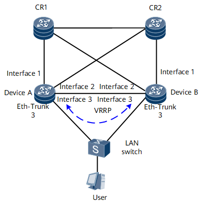
On the network shown in Figure 1, users access Device A and Device B through a LAN switch. The two Devices run VRRP to determine the master/backup status. Basic user access functions are configured on Device A and Device B, allowing the users to go online through the master device. If the master device or the link on the network or user side of the master device fails, service traffic needs to be quickly switched to the backup device.
Interfaces 1 through 3 in this example represent GE 0/1/0, GE 0/1/10, and GE 0/1/2, respectively.
Device |
Interface |
IP Address |
Device A |
Eth-Trunk3.4001 |
192.168.254.2/29 |
Device A |
Loopback 0 |
172.20.1.1/32 |
Device A |
Loopback 10 |
172.20.1.3/32 |
Device A |
Eth-Trunk 2 |
172.20.0.41/30 |
Device A |
GE 0/1/0 |
172.20.0.33/30 |
Device A |
GE 0/1/10 |
172.20.0.57/30 |
Device B |
Eth-Trunk3.4001 |
192.168.254.3/29 |
Device B |
Loopback 0 |
172.20.1.1/32 |
Device B |
Loopback 10 |
172.20.1.2/32 |
Device B |
Eth-Trunk 2 |
172.20.0.42/30 |
Device B |
GE 0/1/0 |
172.20.0.37/30 |
Device B |
GE 0/1/10 |
172.20.0.61/30 |
Configuration Roadmap
The configuration roadmap is as follows:
Configure interfaces and assign IP addresses to them.
Establish a dual-device backup platform.
Configure IP address pool binding.
Bind an RBP to an interface from which the user goes online.
Configure routes to ensure IP connectivity between devices. For details, see HUAWEI NetEngine 8000 F Series Router Configuration Guide - IP Routing.
Data Preparation
To complete the configuration, you need the following data:
VRRP ID
Interface IP addresses of routers that back up each other
Backup ID, which is used together with an RBS to identify the RBP to which the user belongs
Procedure
- Configure interfaces for connecting Device A and Device B to the LAN switch, and assign IP addresses to them.
The configuration on Device A is used as an example. The configuration on Device B is similar to that on Device A.
[~DeviceA]interface GigabitEthernet0/1/3
[*DeviceA-GigabitEthernet0/1/3] description ToSwitch
[*DeviceA-GigabitEthernet0/1/3]undo shutdown
[*DeviceA-GigabitEthernet0/1/3] eth-trunk 3
[*DeviceA-GigabitEthernet0/1/3] commit
[~DeviceA-GigabitEthernet0/1/3] quit
[~DeviceA]interface Eth-Trunk3
[*DeviceA-Eth-Trunk3] description ToSwitch
[*DeviceA-Eth-Trunk3] commit
[~DeviceA-Eth-Trunk3] quit
[~DeviceA]interface Eth-Trunk3.4001
[*DeviceA-Eth-Trunk3.4001] control-vid 4001 dot1q-termination
[*DeviceA-Eth-Trunk3.4001]dot1q termination vid 4001
[*DeviceA-Eth-Trunk3.4001]ip address 192.168.254.2 255.255.255.248
[*DeviceA-Eth-Trunk3.4001] commit
[~DeviceA-Eth-Trunk3.4001] quit
- Configure IP addresses for loopback and interconnection interfaces on Device A and Device B.
Configure IP addresses for loopback interfaces. The configuration on Device A is used as an example. The configuration on Device B is similar to that on Device A.
[~DeviceA]interface loopback10
[*DeviceA-loopback10]ip address 172.20.1.3 255.255.255.255
[*DeviceA-loopback10] commit
[~DeviceA-loopback10] quit
[~DeviceA]interface loopback0
[*DeviceA-loopback0]ip address 172.20.1.1 255.255.255.255
[*DeviceA-loopback0] commit
[~DeviceA-loopback0] quit
Configure IP addresses for interconnection interfaces. The configuration on Device A is used as an example. The configuration on Device B is similar to that on Device A.
[~DeviceA]interface GigabitEthernet0/1/2
[*DeviceA-GigabitEthernet0/1/2] description BackupDevice
[*DeviceA-GigabitEthernet0/1/2]undo shutdown
[*DeviceA-GigabitEthernet0/1/2] eth-trunk 2
[*DeviceA-GigabitEthernet0/1/2] commit
[~DeviceA-GigabitEthernet0/1/2] quit
[~DeviceA]interface Eth-Trunk2
[*DeviceA-Eth-Trunk2] description BackupDevice
[*DeviceA-Eth-Trunk2]ip address 172.20.0.41 255.255.255.252
[*DeviceA-Eth-Trunk2] commit
[~DeviceA-Eth-Trunk2] quit
- Establish a dual-device backup platform. The configuration on Device A is used as an example. The configuration on Device B is similar to that on Device A.
In this example, only RUI-related configuration is described. For other configurations, see the corresponding configuration guide.
# Configure a BFD session on the access side to rapidly detect faults in interfaces or links and trigger a master/backup VRRP switchover. 192.168.254.3 is the IP address of Eth-Trunk 3.4001 on Device B.
[~DeviceA] bfd
[*DeviceA-bfd] quit
[*DeviceA]bfd eth-trunk3-peer bind peer-ip 192.168.254.3 source-ip 192.168.254.2
[*DeviceA-bfd-session-bfd] discriminator local 2
[*DeviceA-bfd-session-bfd] discriminator remote 3
[*DeviceA-bfd-session-bfd] commit
[~DeviceA-bfd-session-bfd] quit
# Configure a VRRP group on Eth-Trunk 3.4001, and configure the VRRP group to track the BFD session and network-side interface.
[~DeviceA] interface Eth-Trunk3.4001
[*DeviceA-Eth-Trunk3.4001] vrrp vrid 3 virtual-ip 192.168.254.1
[*DeviceA-Eth-Trunk3.4001] admin-vrrp vrid 3
[*DeviceA-Eth-Trunk3.4001] vrrp vrid 3 priority 120
[*DeviceA-Eth-Trunk3.4001] vrrp vrid 3 preempt-mode timer delay 1200
[*DeviceA-Eth-Trunk3.4001] vrrp vrid 3 track interface GigabitEthernet0/1/0 reduced 30
[*DeviceA-Eth-Trunk3.4001] vrrp vrid 3 track bfd-session 2 peer
[*DeviceA-Eth-Trunk3.4001] vrrp recover-delay 20
[*DeviceA-Eth-Trunk3.4001] commit
[~DeviceA-Eth-Trunk3.4001] quit
Different priorities must be configured for devices in a VRRP group. The device with a higher priority is the master device.
# Configure an RBS.
[~DeviceA] remote-backup-service rbs_qhmd
[*DeviceA-rm-backup-rbs_qhmd] peer 172.20.1.2 source 172.20.1.3 port 2046
[*DeviceA-rm-backup-rbs_qhmd] commit
[~DeviceA-rm-backup-rbs_qhmd] track interface GigabitEthernet0/1/0
[*DeviceA-rm-backup-rbs_qhmd] track interface GigabitEthernet0/1/10
[*DeviceA-rm-backup-rbs_qhmd] protect redirect ip-nexthop 172.20.0.42 interface Eth-Trunk2
[*DeviceA-rm-backup-rbs_qhmd] commit
[~DeviceA-rm-backup-rbs_qhmd] quit
Ensure that the master and backup devices can ping each other.
# Configure an RBP.
[~DeviceA] remote-backup-profile rbp3
[*DeviceA-rm-backup-prf-rbp3] service-type bras
[*DeviceA-rm-backup-prf-rbp3] backup-id 3 remote-backup-service rbs_qhmd
[*DeviceA-rm-backup-prf-rbp3] peer-backup hot
[*DeviceA-rm-backup-prf-rbp3] vrrp-id 3 interface Eth-Trunk3.4001
[*DeviceA-rm-backup-prf-rbp3] nas logic-port Gigabitethernet 0/1/3
[*DeviceA-rm-backup-prf-rbp3] nas logic-sysname MasterDevice
[*DeviceA-rm-backup-prf-rbp3] nas logic-ip 172.20.1.1
[*DeviceA-rm-backup-prf-rbp3] commit
[~DeviceA-rm-backup-prf-rbp3] quit
- Configure IP address pool binding. The configuration on Device A is used as an example. The configuration on Device B is similar to that on Device A.
To configure an address pool on the slave device, run the ip pool ip-pool-name bas { local | remote } rui-slave command.
# Configure an address pool.
[~DeviceA] ip pool dmtjs_xi bas local
[*DeviceA-ip-pool-dmtjs_xi] gateway 192.168.1.1 255.255.255.0
[*DeviceA-ip-pool-dmtjs_xi] section 0 192.168.1.2 192.168.1.254
[*DeviceA-ip-pool-dmtjs_xi] dns-server 192.168.1.1
[*DeviceA-ip-pool-dmtjs_xi] commit
[~DeviceA-ip-pool-dmtjs_xi] quit
# Bind the address pool to the RBP.
[~DeviceA] remote-backup-service rbs_qhmd
[*DeviceA-rm-backup-service rbs_qhmd] commit
[*DeviceA-rm-backup-service rbs_qhmd] ip-pool dmtjs_xi metric 10
[*DeviceA-rm-backup-service rbs_qhmd] commit
[~HUAWEI-backup-service rbs_qhmd] quit
- Configure authentication and accounting policies for user access. The configuration on Device A is used as an example. The configuration on Device B is similar to that on Device A.
[~DeviceA] aaa
[*DeviceA-aaa]  authentication-scheme wu
[*DeviceA-aaa-authen-wu] authentication-mode none
[*DeviceA-aaa-authen-wu] commit
[~DeviceA-aaa-authen-wu] quit
[*DeviceA-aaa]  accounting-scheme wu
[*DeviceA-aaa-accounting-wu] accounting-mode none
[*DeviceA-aaa-accounting-wu] commit
[~DeviceA-aaa-accounting-wu] quit
[*DeviceA-aaa]  domain dmtjs_xi
[*DeviceA-aaa-dmtjs_xi] authentication-scheme wu
[*DeviceA-aaa-dmtjs_xi] accounting-scheme wu
[*DeviceA-aaa-dmtjs_xi] ip-pool dmtjs_xi
[*DeviceA-ip-pool-dmtjs_xi] commit
[~DeviceA-ip-pool-dmtjs_xi] quit
- Bind the RBP to Eth-Trunk3.501 from which users go online. The configuration on Device A is used as an example. The configuration on Device B is similar to that on Device A.
[~DeviceA] interface Eth-Trunk3.501
[*DeviceA-Eth-Trunk3.501] user-vlan 1
[*DeviceA-Eth-Trunk3.501-vlan-1-1] remote-backup-profile rbp3
[*DeviceA-Eth-Trunk3.501-vlan-1-1] quit
[*DeviceA-Eth-Trunk3.501] bas
[*DeviceA-Eth-Trunk3.501-bas]access-type layer2-subscriber default-domain authentication dmtjs_xi
[*DeviceA-Eth-Trunk3.501-bas] authentication-method bind
[*DeviceA-Eth-Trunk3.501-bas] commit
[~DeviceA-Eth-Trunk3.501-bas] quit
- Configure advertisement of address pool routes. The configuration on Device A is used as an example. The configuration on Device B is similar to that on Device A.
[~DeviceA] ospf 1
[*DeviceA-ospf-1] import-route unr
[*DeviceA-ospf-1] area 0
[*DeviceA-ospf-1-area-0.0.0.0] network 172.20.1.1 0.0.0.0
[*DeviceA-ospf-1-area-0.0.0.0] network 172.20.1.3 0.0.0.0
[*DeviceA-ospf-1-area-0.0.0.0] network 172.20.0.36 0.0.0.3
[*DeviceA-ospf-1-area-0.0.0.0] network 172.20.0.40 0.0.0.3
[*DeviceA-ospf-1-area-0.0.0.0] network 172.20.0.60 0.0.0.3
[*DeviceA-ospf-1-area-0.0.0.0] commit
[~DeviceA-ospf-1-area-0.0.0.0] quit
- Verify the configuration.
After successfully configuring the RBP, run the display remote-backup-profile command. According to the command output, the RBS type is bras, the RBP named rbp3 is bound to Eth-Trunk3.501 from which users go online, and Device A is in the Master state.
<DeviceA> display remote-backup-profile rbp3
-----------------------------------------------
 Profile-Index        : 0x802
 Profile-Name         : rbp3
 Service              : bras
 Remote-backup-service: service1
 Backup-ID            : 10
 track protocol       : VRRP
 VRRP-ID              : 3
 VRRP-Interface       : Eth-Trunk3.4001
 Interface            :
                       Eth-Trunk3.501
 State           	 : Master
 Peer-state      	 : Slave
 Backup mode          : hot
 Slot-Number          : 1
 Card-Number          : 0
 Port-Number          : 0
 Nas logic-port       : Gigabitethernet 0/1/3
 Nas logic-ip         : 172.20.1.1
 Nas logic-sysname    : MasterDevice
 Traffic interval     : 10(minutes)
After successfully configuring the RBS, run the display remote-backup-service command. According to the command output, the TCP connection is in the Connected state.
<DeviceA> display remote-backup-service rbs_qhmd
----------------------------------------------------------
 Service-Index    : 0
 Service-Name     : rbs_qhmd
 TCP-State        : Connected
 Peer-ip          : 172.20.1.2
 Source-ip        : 172.20.1.3
 TCP-Port         : 2046
 Track-BFD        : --
 Track-interface0 : 0/1/0
                  Weight : 10
 Track-interface1 : 0/1/10
                  Weight : 10
 SSL-Policy-Name  : --
 SSL-State        : --
Uplink state     : 2 (1:DOWN 2:UP)
 Domain-map-list  : --
----------------------------------------------------------

 ip pool:
         dmtjs_xi metric 10
 ipv6 pool:
 Failure ratio    : 100%
 Failure duration : 0 min
--------------------------------------------------------
After users go online, run the display backup-user command to view user information that is backed up.
<DeviceA> display backup-user
  Remote-backup-service: rbs3
  Total Users Numer: 3
------------------------------------------------------------------------
 100     101     102
------------------------------------------------------------------------
Run the display access-user interface command to view online user information on a specified interface.
<DeviceA> display access-user interface Eth-Trunk.501
------------------------------------------------------------------------------
  UserID  Username              Interface       IP address       MAC                   IPv6 address
  ------------------------------------------------------------------------------
  --------------------------------------------------------------------------
  100     user1@dmtjs_xi        Eth-Trunk.501   192.168.1.10     00e0-fc12-0101          -
  101     user2@dmtjs_xi        Eth-Trunk.501   192.168.1.9      00e0-fc12-0102          -
  102     user3@dmtjs_xi        Eth-Trunk.501   192.168.1.8      00e0-fc12-0103          -
  --------------------------------------------------------------------------
  Total users                        :3
Configuration Files
Device A configuration file
#
 sysname DeviceA
#
router id 172.20.1.3
#
vlan batch 2 to 9 11 to 504 506 to 3999 4001 to 4094
#
bfd
#
ip pool dmtjs_xi bas local
gateway 192.168.1.1 255.255.255.0
section 0 192.168.1.2 192.168.1.254
dns-server 192.168.1.1
#
aaa
 authentication-scheme wu
 authentication-mode none
 accounting-scheme wu
accounting-mode none
 domain dmtjs_xi
 authentication-scheme wu
 authentication-scheme wu
 ip-pool dmtjs_xi
#
bfd eth-trunk3-peer bind peer-ip 192.168.254.3 source-ip 192.168.254.2
 discriminator local 2
 discriminator remote 3
#
interface GigabitEthernet0/1/3
description ToSwitch
undo shutdown
eth-trunk 3
interface Eth-Trunk3.4001
 encapsulation 4001 dot1q-termination
 dot1q termination vid 4001
ip address 192.168.254.2 255.255.255.248
vrrp vrid 3 virtual-ip 192.168.254.1
 admin-vrrp vrid 3
 vrrp vrid 3 priority 120
 vrrp vrid 3 preempt-mode timer delay 1200
 vrrp vrid 3 track bfd-session 2 peer
 vrrp vrid 3 track interface GigabitEthernet0/1/0 reduced 30
 vrrp recover-delay 2
#
interface LoopBack0
 ip address 172.20.1.1 255.255.255.255
#
interface LoopBack10
 ip address 172.20.1.3 255.255.255.255
#
interface GigabitEthernet0/1/0
undo shutdown
 ip address 172.20.0.33 255.255.255.252
#
interface GigabitEthernet0/1/10
undo shutdown
 ip address 172.20.0.57 255.255.255.252
#
interface GigabitEthernet0/1/2
undo shutdown
eth-trunk 2
#
interface Eth-Trunk2
description BackupDevice
ip address 172.20.0.41 255.255.255.252
#
remote-backup-service rbs_qhmd
 peer 172.20.1.2 source 172.20.1.3 port 2046
 track interface gigabitethernet 0/1/0
 track interface gigabitethernet 0/1/10
 protect redirect ip-nexthop 172.20.0.42 interface Eth-Trunk2
 ip-pool dmtjs_xi metric 10
#
remote-backup-profile rbp3
 service-type bras
 backup-id 3 remote-backup-service rbs_qhmd
 peer-backup hot
 vrrp-id 3 interface Eth-Trunk3.4001
 nas logic-port gigabitethernet0/1/3
 nas logic-sysname MasterDevice
 nas logic-ip 172.20.1.1
#
interface Eth-Trunk3.501
 user-vlan 501
 remote-backup-profile rbp3
 bas
  access-type layer2-subscriber default-domain authentication dmtjs_xi
  authentication-method bind
 #
#
ospf 1
 import-route unr
 area 0.0.0.0
  network 172.20.0.36 0.0.0.3
  network 172.20.0.60 0.0.0.3
  network 172.20.0.40 0.0.0.3
  network 172.20.1.1 0.0.0.0
  network 172.20.1.3 0.0.0.0
#
 return
Device B configuration file
#
 sysname DeviceB
#
router id 172.20.1.2
#
vlan batch 2 to 9 11 to 504 506 to 3999 4001 to 4094
#
bfd
#
ip pool dmtjs_xi bas local rui-slave
gateway 192.168.1.1 255.255.255.0
section 0 192.168.1.2 192.168.1.254
dns-server 192.168.1.1
#
aaa
 authentication-scheme wu
 authentication-mode none
 accounting-scheme wu
accounting-mode none
 domain dmtjs_xi
 authentication-scheme wu
 authentication-scheme wu
 ip-pool dmtjs_xi
#
bfd eth-trunk3-peer bind peer-ip 192.168.254.2 source-ip 192.168.254.3
 discriminator local 3
 discriminator remote 2
#
interface GigabitEthernet0/1/3
description ToSwitch
undo shutdown
eth-trunk 3
interface Eth-Trunk3.4001
 control-vid 4001 dot1q-termination
 dot1q termination vid 4001
ip address 192.168.254.3 255.255.255.248
vrrp vrid 3 virtual-ip 192.168.254.1
 admin-vrrp vrid 3
 vrrp vrid 3 track bfd-session 3 peer
#
interface LoopBack0
 ip address 172.20.1.1 255.255.255.255
#
interface LoopBack10
 ip address 172.20.1.2 255.255.255.255
#
interface GigabitEthernet0/1/0
undo shutdown
 ip address 172.20.0.37 255.255.255.252
#
interface GigabitEthernet0/1/10
undo shutdown
 ip address 172.20.0.61 255.255.255.252
#
interface GigabitEthernet0/1/2
undo shutdown
eth-trunk 2
#
interface Eth-Trunk2
description MasterDevice
ip address 172.20.0.42 255.255.255.252
#
remote-backup-service rbs_qhmd
 peer 172.20.1.3 source 172.20.1.2 port 2046
 track interface gigabitethernet 0/1/0
 track interface gigabitethernet 0/1/10
 protect redirect ip-nexthop 172.20.0.41 interface Eth-Trunk2
 ip-pool dmtjs_xi metric 20
#
remote-backup-profile rbp3
 service-type bras
 backup-id 3 remote-backup-service rbs_qhmd
 peer-backup hot
 vrrp-id 3 interface Eth-Trunk3.4001
 nas logic-port gigabitethernet0/1/3
 nas logic-sysname MasterDevice
 nas logic-ip 172.20.1.1
#
interface Eth-Trunk3.501
 user-vlan 501
 remote-backup-profile rbp3
 bas
  access-type layer2-subscriber default-domain authentication dmtjs_xi
  authentication-method bind
 #
#
ospf 1
 import-route unr
 area 0.0.0.0
  network 172.20.0.36 0.0.0.3
  network 172.20.0.60 0.0.0.3
  network 172.20.0.40 0.0.0.3
  network 172.20.1.2 0.0.0.0
  network 172.20.1.3 0.0.0.0
#
 return