Example for Configuring Dual-device Hot Backup for Layer 3 Static IPv4 Users
This section provides an example for configuring dual-device hot backup for Layer 3 static IPv4 users and a networking diagram for understanding usage scenarios and configuration procedures.
Usage Scenario
High reliability is a basic requirement for carrier-class devices. The NetEngine 8000 F that functions as a service aggregation router carries multiple services, such as HSI, VoIP, and IPTV. It connects to a core network to implement Layer 3 routing functions and to the aggregation layer to terminate Layer 2 user packets for user access. The NetEngine 8000 F therefore must have high reliability. Although the NetEngine 8000 F can ensure non-stop data flow forwarding, this does not guarantee interruption-free user services. If a network node or link fails and user information is not synchronized to a backup device, user services will be interrupted. To prevent this problem, dual-device hot backup is introduced.
Networking Requirements
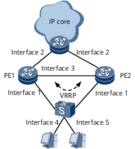
As shown in Figure 1, users access PE1 and PE2 through the CE. An Eth-Trunk interface is configured on each PE, and the two PEs are directly connected. A VRRP group is configured on PE1 and PE2 to track the status of Eth-Trunk member interfaces. Access links are bundled together on the CE, and the LACP protocol is run to work with the PEs to select the active and standby links. This ensures that services can be immediately switched to the backup device if the master device fails after users go online.

In this example, interfaces 1 through 5 represent GE 0/1/0, GE 0/1/1, GE 0/1/5, GE 0/1/8, and GE 0/1/11, respectively.
Device Name |
Interface Name |
IP Address and Mask |
PE1 |
GE 0/1/0 |
Eth-Trunk member interface |
PE1 |
GE 0/1/1 |
10.1.1.1/24 (network-side interface) |
PE1 |
GE 0/1/5 |
10.193.2.2/24 (IP address of the interface running VRRP) |
PE1 |
Loopback1 |
172.16.18.1/32 (IP address of PE1's interface with an RBS deployed) |
PE2 |
GE 0/1/0 |
Eth-Trunk member interface |
PE2 |
GE 0/1/1 |
10.1.1.2/24 (network-side interface) |
PE2 |
GE 0/1/5 |
10.193.2.1/24 (IP address of the interface running VRRP) |
PE2 |
Loopback2 |
172.16.18.2/32 (IP address of PE2's interface with an RBS deployed) |
Configuration Roadmap
The configuration roadmap is as follows:
Configure basic user access functions and ensure that the two devices working in master/back mode have the same configuration. For configuration details, see HUAWEI NetEngine 8000 F SeriesRouter Configuration Guide > User Access.
Configure Eth-Trunk interfaces to work in static LACP mode. For configuration details, see HUAWEI NetEngine 8000 F SeriesRouter Configuration Guide > LAN Access and MAN Access.
Configure a VRRP group on PE1 and PE2.
Configure VRRP to track the interface status.
Associate the Eth-Trunk interfaces working in static LACP mode on the PEs with the VRRP group.
Data Preparation
To complete the configuration, you need the following data:
VRRP ID
IP address of each interface on PE1 and PE2
Backup ID, which works together with an RBS to identify an RBP to which users belong
User access parameters
Procedure
- Configure user access.
For configuration details, see HUAWEI NetEngine 8000 F SeriesRouter Configuration Guide > User Guide > AAA and User Management Configuration.
- Configure Eth-Trunk interfaces to work in static LACP mode, and add the member interfaces GE0/1/8 and GE0/1/11 to the Eth-Trunk interfaces.
# Configure CE1.
<HUAWEI> system-view
[~HUAWEI] sysname CE1
[*HUAWEI] commit
[~CE1] interface Eth-Trunk 20
[*CE1-Eth-Trunk20] mode lacp-static
[*CE1-Eth-Trunk20] lacp timeout fast
[*CE1-Eth-Trunk20] trunkport gigabitethernet 0/1/8 to 0/1/11
[*CE1-Eth-Trunk20] commit
[~CE1-Eth-Trunk20] quit
# Configure PE1.
<HUAWEI> system-view
[~HUAWEI] sysname PE1
[*HUAWEI] commit
[~PE1] interface Eth-Trunk 10
[*PE1-Eth-Trunk10] mac-address 00e0-fc12-3456
[*PE1-Eth-Trunk10] mode lacp-static
[*PE1-Eth-Trunk10] lacp timeout fast
[*PE1-Eth-Trunk10] trunkport gigabitethernet 0/1/0
[*PE1-Eth-Trunk10] commit
[~PE1-Eth-Trunk10] quit
# Configure PE2.
<HUAWEI> system-view
[~HUAWEI] sysname PE2
[*HUAWEI] commit
[~PE2] interface Eth-Trunk 12
[*PE2-Eth-Trunk12] mac-address 00e0-fc12-3456
[*PE2-Eth-Trunk12] mode lacp-static
[*PE2-Eth-Trunk12] lacp timeout fast
[*PE2-Eth-Trunk12] trunkport gigabitethernet 0/1/0
[*PE2-Eth-Trunk12] commit
[~PE2-Eth-Trunk12] quit
- Configure an mVRRP group.
# On PE1, configure an mVRRP group and bind it to the GE interface. Set the IPaddress of the GE interface to 10.193.2.2, the virtual IP address to10.193.2.100, and the VRRP priority to 120 in the VRRP group so that PE1 functions as the master device.
[~PE1] interface Gigabitethernet 0/1/5
[~PE1-Gigabitethernet0/1/5] undo shutdown
[*PE1-Gigabitethernet0/1/5] ip address 10.193.2.2 255.255.255.0
[*PE1-Gigabitethernet0/1/5] vrrp vrid 120 virtual-ip 10.193.2.100
[*PE1-Gigabitethernet0/1/5] vrrp vrid 120 priority 120
[*PE1-Gigabitethernet0/1/5] admin-vrrp vrid 120 ignore-if-down
[*PE1-Gigabitethernet0/1/5] commit
# On PE2, configure an mVRRP group and bind it to the GE interface. Set the IP address of the GE interface to10.193.2.1 and the virtual IP address to 10.193.2.100, and use the defaultVRRP priority in the VRRP group so that PE2 functions as the backup device.
[~PE2] interface Gigabitethernet 0/1/5
[*PE2-Gigabitethernet0/1/5] undo shutdown
[*PE2-Gigabitethernet0/1/5] ip address 10.193.2.1 255.255.255.0
[*PE2-Gigabitethernet0/1/5] vrrp vrid 120 virtual-ip 10.193.2.100
[*PE2-Gigabitethernet0/1/5] admin-vrrp vrid 120 ignore-if-down
[*PE2-Gigabitethernet0/1/5] commit
- Configure the VRRP group to track the interface status.
# Configure VRRP on PE1 to track the interface status.
[~PE1-Gigabitethernet0/1/5] vrrp vrid 120 track interface Gigabitethernet 0/1/0 reduced 40
[~PE1-Gigabitethernet0/1/5] vrrp vrid 120 track interface Gigabitethernet 0/1/1 reduced 40
[*PE1-Gigabitethernet0/1/5] commit
[~PE1-Gigabitethernet0/1/5] quit
# Configure VRRP on PE2 to track the interface status.
[~PE2-Gigabitethernet0/1/5] vrrp vrid 120 track interface Gigabitethernet 0/1/1 reduced 40
[~PE2-Gigabitethernet0/1/5] vrrp vrid 120 track interface Gigabitethernet 0/1/0 reduced 40
[*PE2-Gigabitethernet0/1/5] commit
[~PE2-Gigabitethernet0/1/5] quit
- Associate the Eth-Trunk interfaces working in static LACP mode with the VRRP group.
# Associate PE1's Eth-Trunk interface working in static LACP mode with the VRRP group.
[~PE1] interface Eth-Trunk 10
[*PE1-Eth-Trunk 10] lacp track vrrp vrid 120 interface Gigabitethernet 0/1/5
[*PE1-Eth-Trunk 10] commit
[~PE1-Eth-Trunk 10] quit
# Associate PE2's Eth-Trunk interface working in static LACP mode with the VRRP group.
[~PE2] interface Eth-Trunk 12
[*PE2-Eth-Trunk 12] lacp track vrrp vrid 1 interface Gigabitethernet 0/1/5
[*PE2-Eth-Trunk 12] commit
[~PE2-Eth-Trunk 12] quit
- Configure an IP address pool.
# Configure an address pool named ln.
[~PE1] ip pool ln bas local
[*PE1-ip-pool-ln] gateway 10.0.0.1 255.255.255.0
[*PE1-ip-pool-ln] section 10.0.0.2 10.0.0.255
[*PE1-ip-pool-ln] excluded-ip-address 10.0.0.2 10.0.0.254
[*PE1-ip-pool-ln] commit
[~PE1-ip-pool-ln] quit
- Configure an RBS and an RBP. The command output on PE1 is used as an example.
# Configure an RBS named s1.
[~PE1] remote-backup-service s1
[*PE1-rm-backup-srv-s1] peer 172.16.18.1 source 172.16.18.2 port 12012
[*PE1-rm-backup-srv-s1] track interface GigabitEthernet 0/1/1
[*PE1-rm-backup-srv-s1] commit
[~PE1-rm-backup-srv-s1] quit
Configure an RBP named p1.
[~PE1] remote-backup-profile p1
[*PE1-rm-backup-prf-p1] service-type bras
[*PE1-rm-backup-prf-p1] backup-id 1 remote-backup-service s1
[*PE1-rm-backup-prf-p1] peer-backup hot
[*PE1-rm-backup-prf-p1] vrrp-id 1 interface gigabitethernet 0/1/5
[*PE1-rm-backup-prf-p1] ip-pool ln
[*PE1-rm-backup-prf-p1] commit
[~PE1-rm-backup-prf-p1] quit
- Configure a user-side interface.
# On PE1, configure Layer 3 static users to be triggered to go online through IP packets.
[~PE1] layer3-subscriber 200.0.0.1 10.0.0.254 domain-name test_hou
[*PE1] interface Eth-Trunk 10.1
[*PE1-Eth-Trunk 10.1] vlan-type dot1q 10
[*PE1-Eth-Trunk 10.1] ip address 10.101.0.1 255.255.255.0
[*PE1-Eth-Trunk 10.1] bas
[*PE1-Eth-Trunk 10.1-bas] access-type layer3-subscriber default-domain pre-authentication test authentication test_hou
[*PE1-Eth-Trunk 10.1-bas] commit
# On PE2, configure Layer 3 static users to be triggered to go online through IP packets.
[~PE2] layer3-subscriber 10.0.0.1 10.0.0.254 domain-name test_hou
[*PE2] interface Eth-Trunk 12.1
[*PE2-Eth-Trunk 12.1] vlan-type dot1q 10
[*PE2-Eth-Trunk 12.1] ip address 10.101.0.1 255.255.255.0
[*PE2-Eth-Trunk 12.1] bas
[*PE2-Eth-Trunk 12.1-bas] access-type layer3-subscriber default-domain pre-authentication test authentication test_hou
[*PE2-Eth-Trunk 12.1-bas] commit
- Verify the configuration.
After completing the configurations, run the display remote-backup-profile command. The command output shows that the status of PE1 is Master and that of PE2 is Slave.
<PE1> display remote-backup-profile p1
-----------------------------------------------
 Profile-Index        : 0x1000
 Profile-Name         : p1
 Service              : bras
 Remote-backup-service: s1
 Backup-ID            : 1
 track protocol       : VRRP
 VRRP-ID              : 120
 VRRP-Interface       : GigabitEthernet0/1/5
 Access-Control       : --
 State                : Slave
 Peer State           : Master
 Interface            :
                        Eth-Trunk12.2
                        Eth-Trunk12.111
 Backup mode          : hot
 Slot-Number          : --
 Card-Number          : --
 Port-Number          : --
 Traffic threshold    : 50(MB)
 Traffic interval     : 10(minutes)
 IP-Pool              :
                        ln
 Forwarding Configured: Slave Forwarding
<PE1> display remote-backup-service S1
----------------------------------------------------------
 Service-Index    : 1
 Service-Name     : s1
 TCP-State        : Connected
 Peer-ip          : 172.16.18.2
 Source-ip        : 172.16.18.1
 TCP-Port         : 12012
 Track-BFD        : -
 SSL-Policy-Name  : --
 SSL-State        : --
 Last up time     : 2016-08-02 15:34:36
 Track-interface0 : GigabitEthernet0/1/1
                    Weight : 10
 Uplink state     : 2 (1:DOWN 2:UP)
 Domain-map-list  : --
 Send Q pkt count : 0
----------------------------------------------------------

 ip pool:
 ipv6 pool:
 Failure ratio    : 100%
 Failure duration : 0 min
 pool route status: 2
 switch mark      : 2
----------------------------------------------------------
 Rbs-ID         : 0
 Protect-type   : public(unknown)
 Tunnel-policy  : yhz
 Peer-ip        : 172.16.18.2
 Vrfid          : 0
 Tunnel-state   : DOWN
 Tunnel-OperFlag: NORMAL
 Spec-interface : Null
 Total users    : 0
Configuration Files
PE1 configuration file
#
sysname PE1
#
aaa
 domain huawei
  authentication-scheme default0
  accounting-scheme default0
  ip-pool ln
#
ip pool ln bas local
 gateway 10.0.0.1 255.255.255.0
 section 0 10.0.0.2 10.0.0.255
 excluded-ip-address 10.0.0.2 10.0.0.254
#
remote-backup-service s1
 peer 172.16.18.1 source 172.16.18.2 port 12012
 track interface GigabitEthernet0/1/1
#
remote-backup-profile p1
 service-type bras
 backup-id 1 remote-backup-service s1
 peer-backup hot
 vrrp-id 120 interface GigabitEthernet0/1/5
 ip-pool ln
#
layer3-subscriber 10.0.0.2 10.0.0.254 domain-name test
#
interface Eth-Trunk10
 mac-address 00e0-fc12-3456
 mode lacp-static
 lacp timeout fast
 lacp track vrrp vrid 120 interface GigabitEthernet0/1/5
#
interface Eth-Trunk 10.1
 vlan-type dot1q 10
 ip address 172.18.18.1 0.0.0.0
 bas
 #
  access-type layer3-subscriber default-domain pre-authentication test authentication test_hou
 #
#
interface GigabitEthernet0/1/1
 undo shutdown
 ip address 10.1.1.2 255.255.255.0

#
interface GigabitEthernet0/1/0
 undo shutdown
 eth-trunk 10
 dcn
#
interface GigabitEthernet0/1/1
 undo shutdown
 ip address 10.1.1.2 255.255.255.0

#
interface GigabitEthernet0/1/5
 undo shutdown
 ip address 10.193.2.2 255.255.255.0
 vrrp vrid 120 virtual-ip 10.193.2.100
 admin-vrrp vrid 120 ignore-if-down
 vrrp vrid 120 priority 120
 vrrp vrid 120 track interface GigabitEthernet0/1/0 reduced 40
 vrrp vrid 120 track interface GigabitEthernet0/1/1 reduced 40
 dcn
#
#
ospf 1
 default cost inherit-metric
 import-route direct
 import-route unr
 area 0.0.0.0
  network 10.1.1.0 0.0.0.255
  network 10.1.3.0 0.0.0.255
#
PE2 configuration file
#
sysname PE2
#
aaa
 domain huawei
  authentication-scheme default0
  accounting-scheme default0
  ip-pool ln
#
ip pool ln bas local
 gateway 10.0.0.1 255.255.255.0
 section 0 10.0.0.2 10.0.0.255
 excluded-ip-address 10.0.0.2 10.0.0.254
#
remote-backup-service s2
 peer 172.16.18.2 source 172.16.18.1 port 12012
 track interface GigabitEthernet0/1/1
#
interface Eth-Trunk12
 mac-address 00e0-fc12-3456
 mode lacp-static
 lacp timeout fast
 lacp track vrrp vrid 120 interface GigabitEthernet0/1/5
#
interface Eth-Trunk 12.1
 vlan-type dot1q 10
 ip address 172.16.18.2 0.0.0.0
 bas
 #
  access-type layer3-subscriber default-domain pre-authentication test authentication test_hou
 #
#
interface GigabitEthernet0/1/1
 undo shutdown
 ip address 10.1.1.2 255.255.255.0
#
interface GigabitEthernet0/1/0
 undo shutdown
 eth-trunk 12
 dcn
#
interface GigabitEthernet0/1/5
 undo shutdown
vrrp vrid 120 virtual-ip 10.193.2.100
 admin-vrrp vrid 120 ignore-if-down
 vrrp vrid 120 track interface GigabitEthernet0/1/0
 vrrp vrid 120 track interface GigabitEthernet0/1/1 reduced 40
 dcn
#
#
ospf 1
 default cost inherit-metric
 import-route direct
 import-route unr
 area 0.0.0.0
  network 10.1.1.0 0.0.0.255
  network 10.1.1.0 0.0.0.255
  network 10.1.3.0 0.0.0.255
#
interface Loopback1
 undo shutdown
 ip address 172.16.18.1 255.255.255.0
#