General Architecture of FlexE
The FlexE standards define the client/group architecture, as shown in Figure 1. Multiple FlexE clients can be mapped to a group of PHYs (FlexE group) for data transmission. Owing to the IEEE 802.3-defined Ethernet technology, the FlexE architecture provides enhanced functions based on existing Ethernet MAC and PHY layers.
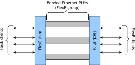
FlexE involves three concepts: FlexE client, FlexE shim, and FlexE group.
- FlexE client: corresponds to an externally observed user interface that functions in the same way as traditional service interfaces on existing IP/Ethernet networks. FlexE clients can be configured flexibly to meet specific bandwidth requirements. They support Ethernet MAC data streams of various rates (including 10 Gbit/s, 40 Gbit/s, N x 25 Gbit/s, and even non-standard rates), and the Ethernet MAC data streams are transmitted to the FlexE shim layer as 64B/66B encoded bit streams.
- FlexE shim: functions as a layer that maps or demaps the FlexE clients carried over a FlexE group. It decouples the MAC and PHY layers and implements key FlexE functions through calendar timeslot distribution.
- FlexE group: consists of various Ethernet PHYs defined in IEEE 802.3. By default, the PHY bandwidth is divided based on the 5 Gbit/s timeslot granularity.