Interconnection Between FlexE and Optical Transmission Devices
FlexE interfaces function as UNIs connecting routers to optical transmission devices. Flexible rate matching can be used to implement a one-to-one correspondence between the bandwidth of data flows actually carried by the UNIs and the bandwidth of the links of NNIs on the optical transmission devices. This greatly simplifies the mapping of the FlexE interfaces of the routers on the optical transmission devices, reducing device complexity as well as cutting capital expenditure (CAPEX) and operating expense (OPEX).
The FlexE standards define three modes for interconnection with optical transmission devices: unaware, termination, and aware. Currently, the unaware mode is recommended.
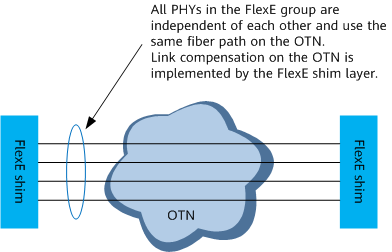
Unaware Mode
Optical transmission devices carry mappings according to the bit transparent transmission mechanism, as shown in Figure 1. The unaware mode applies to scenarios where the Ethernet rate is the same as the wavelength rate of colored optical modules. It provides FlexE support without requiring hardware upgrades, fully utilizing legacy optical transmission devices. In addition, it can use FlexE bonding to provide E2E ultra-high bandwidth channels across OTNs.
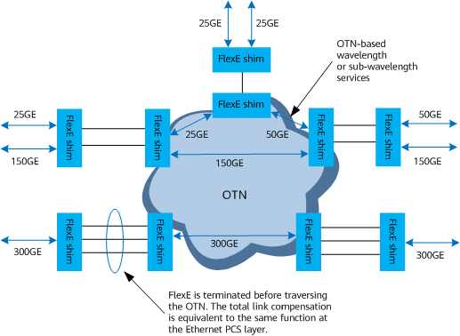
Termination Mode
FlexE is terminated on the ingress interfaces of optical transmission devices. The OTN detects FlexE UNIs, restores the FlexE client data flows, and further maps the data flows to the optical transmission devices for transmission, as shown in Figure 2. This mode is the same as the mode in which standard Ethernet interfaces are carried over the OTN, and can implement traffic grooming for different FlexE clients on the OTN.
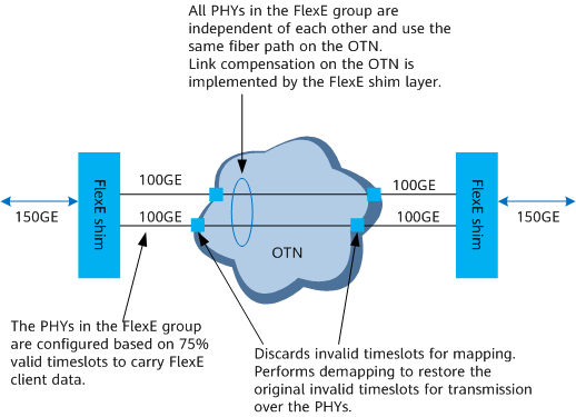
Aware Mode
The aware mode mainly uses the FlexE sub-rating function and is applicable to scenarios where the single-wavelength rate of colored optical modules is lower than the rate of an Ethernet interface. As shown in Figure 3, 150 Gbit/s data flows need to be transmitted between routers and optical transmission devices. In this case, two 100GE PHYs can be bonded to form a FlexE group. The PHYs in the FlexE group are configured based on 75% valid timeslots, and the remaining 25% timeslots are filled with special error control blocks to indicate that they are invalid.
When FlexE UNIs map data flows to the OTN in aware mode, the OTN directly discards invalid timeslots, extracts the data to be carried based on the bandwidth of the original data flows, and then maps these data flows to the optical transmission devices with matching rates. The configurations of the optical transmission devices must be the same as those of the FlexE UNIs, so that the optical transmission devices can detect the FlexE UNIs for data transmission.