Configuring a Bandwidth Mode for an Interface
Different bandwidth modes can be configured for device interfaces.
Context
- For the NetEngine 8000 F1A
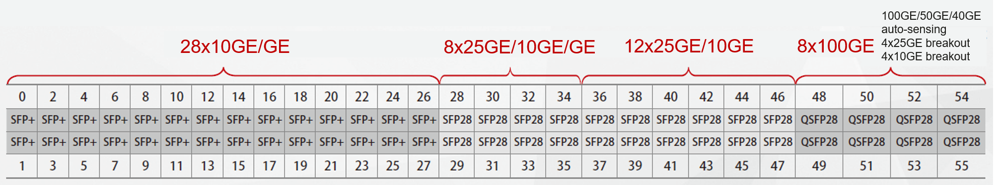
Figure 1 shows the interface layout on the panel.
- Interfaces 0 to 27 work in 10GE mode by default. In addition, they provide GE capabilities.
- Interfaces 28 to 31 belong to an interface group, and interfaces 32 to 35 belong to another one. These interfaces work in 25GE/10GE auto-sensing mode by default. You can run the port-mode card-id card-id group-id group-id modeType command in the slot view to switch the working mode to 10GE/GE auto-sensing for interfaces in an interface group.
- Interfaces 36 to 47 work in 25GE mode by default. In addition, they provide 10GE capabilities.
- Interfaces 48 to 55 work in 100GE mode by default. In addition, they provide 50GE, 40GE, 4 x 10GE breakout, and 4 x 25GE breakout capabilities.
Table 1 lists the bandwidth values and bandwidth modes of interfaces 0 to 55 in various scenarios.
Table 1 Bandwidth values and bandwidth modes of interfaces 0 to 55 in various scenarios Interface
Bandwidth When the License Is Not Activated in Default Mode
Bandwidth Mode When the License Does Not Need to Be Activated
Bandwidth Mode When the License Needs to Be Activated (The Available Bandwidth Is 100M When the License Is Not Activated)
0–27
100M
1GE
10GE
28-35
100M
1GE
10GE and 25GE
36-47
100M
None
10GE and 25GE
48–55
100M
40GE, 50GE, and 4 x 10GE breakout
100GE and 4 x 25GE breakout
- For the NetEngine 8000 F2A
Figure 2 shows the interface layout on the panel.
- Each of interfaces 0 to 7 and 36 to 63 exclusively occupies 100GE bandwidth.
- Each of interfaces 20 to 27 and some of interfaces 8 to 19 and 28 to 35 form one group, which shares 400GE bandwidth.
- Interfaces 20 to 27 work in 400GE mode by default. Interfaces 8 to 19 and 28 to 35 are invisible by default.
- When interfaces 20 to 27 are switched from the 400GE mode to the 100GE/50GE/40GE mode, other interfaces in the same group are created based on the default 100GE mode.

There are eight interface groups, and each group shares 400GE bandwidth.
- Group 1: interface 20 and interfaces 8, 9, and 12
- Group 2: interface 21 and interfaces 10, 11, and 14
- Group 3: interface 22 and interfaces 13, 16, and 17
- Group 4: interface 23 and interfaces 15, 18, and 19
- Group 5: interface 24 and interfaces 28 and 29
- Group 6: interface 25 and interfaces 30 and 31
- Group 7: interface 26 and interfaces 32 and 33
- Group 8: interface 27 and interfaces 34 and 35
Table 2 lists the rates supported by interfaces.
Table 2 Rates supported by interfaces Interface Number
Supported Rate
0–19
100GE/50GE/40GE
20–27
400GE/100GE/50GE/40GE
28-35
100GE/50GE/40GE
36-51
100GE/50GE/40GE/4*25GE/4*10GE
52-63
100GE/50GE/40GE
The bandwidth of interfaces 0 to 63 is controlled by the license. Table 3 lists the default interface bandwidth and the maximum available bandwidth after the license is activated.

Procedure
- Configure bandwidth modes for interfaces.For the NetEngine 8000 F1A, perform the following operations:
- Interfaces 0 to 27: Insert optical modules of the corresponding modes, and use the auto-sensing mode. (The bandwidth mode automatically switches to 1GE or 10GE, depending on the optical module rate.) Alternatively, run the port-mode { 10GE | 1GE } command in the interface view to configure a bandwidth mode for the interface.
- Interfaces 28 to 35: Interfaces 28 to 31 belong to an interface group, and interfaces 32 to 35 belong to another one.
- These interfaces work in 25GE/10GE auto-sensing mode by default. The bandwidth mode automatically switches to 10GE or 25GE, depending on the optical module rate. Alternatively, run the port-mode { 25GE | 10GE } command in the interface view to configure a bandwidth mode for the interface.
- You can run the port-mode card-id card-id group-id group-id modeType command in the slot view to switch the working mode to 10GE/GE auto-sensing for interfaces in an interface group. The bandwidth mode automatically switches to 1GE or 10GE, depending on the optical module rate. Alternatively, run the port-mode { 10GE | 1GE } command in the interface view to configure a bandwidth mode for the interface.
- Interfaces 36 to 47: Insert optical modules of the corresponding modes, and use the auto-sensing mode. (The bandwidth mode automatically switches to 10GE or 25GE, depending on the optical module rate.) Alternatively, run the port-mode { 25GE | 10GE } command in the interface view to configure a bandwidth mode for the interface.
- Interfaces 48 to 55: Insert optical modules of the corresponding modes, and use the auto-sensing mode. (The bandwidth mode automatically switches to 40GE, 50GE, or 100GE, depending on the optical module rate.) Alternatively, run the port split dimension interface { { interface-name1 interface-type interface-number1 } [ to { interface-name2 interface-type interface-number2 } ] } &<1–12> split-type split-type command in the system view to configure a bandwidth mode for specified interfaces.
For the NetEngine 8000 F2A, perform the following operation:- Run the port split dimension interface { { interface-name1 interface-type interface-number1 } [ to { interface-name2 interface-type interface-number2 } ] } &<1–32> split-type split-type command in the system view to configure a bandwidth mode for specified interfaces.
- Activate an interface-specific basic hardware license.
- Run system-view
The system view is displayed.
- Run license
The license view is displayed.
- Run active port-basic slot slot-id card card-id port port-list { 200G | 400G }
The interface-specific basic hardware license for 200GE or 400GE interfaces is activated.
This command takes effect only on the NetEngine 8000 F2A's interfaces 20 to 27, and the default bandwidth is 100GE.
- Run active port-basic slot slot-id card card-id port port-list
The interface-specific basic hardware license is activated.
To deactivate an interface-specific basic hardware license, run the undo active port-basic slot slot-id card card-id [ port port-list ] command in the license view. After the preceding command configuration is committed, the corresponding license resource is released.
For the NetEngine 8000 F1A: If interfaces 28 to 47 work in 10GE mode, you need to apply for the Port 10GE Upgrade RTU license. If they work in 25GE mode, you need to apply for both the Port 10GE Upgrade RTU and Port 25GE Upgrade RTU licenses. For details about the license information, see the configurator.
For the NetEngine 8000 F2A: This command applies only to interfaces 0 to 19 and 28 to 63.
- Run commit
The configuration is committed.
- Run system-view