Example for Configuring L2TP Access in Client-Initialized VPN Scenarios
This section provides an example for configuring L2TP access in client-initiated VPN scenarios.
Networking Requirements
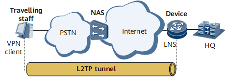
On the network shown in Figure 1, a travelling worker (VPN user) logs in to the NAS through the PSTN, and the NAS is connected to the LNS at the company headquarters through the Internet. The networking requirements are as follows:
The VPN user needs to initiate a tunnel connection request directly to the LNS.
After receiving this connection request, the LNS needs to verify the username and password and assign a private IP address to the VPN user.
The VPN user needs to communicate with the company headquarters through the tunnel between the VPN user and LNS.
The VPN user needs to access the Internet by using domain1 and obtain an IP address from address pool pool1.
Configuration Roadmap
The configuration roadmap is as follows:
Install client software on the user side and configure parameters.
Configure the LNS:
Create a virtual template.
Configure an L2TP group and L2TP attributes.
Configure an address pool and domain.
Configure an LNS group and attributes.
Data Preparation
To complete the configuration, you need the following data:
Username and password on the client and LNS
Loopback address
Name, network segment, and gateway of the address pool
Name of a user access domain

This section provides only the procedures relevant to L2TP.
Procedure
- Configure a dial-up connection on the user side.# Install L2TP client software on the user-side host and dial up to the Internet. Then, perform the following configurations (the configuration process varies with the client software):
Set the VPN username and password to vpdnuser and 1qaz@WSX, respectively.
Set the IP address of the LNS to the IP address of the NetEngine 8000 F interface that connects to the Internet (In this example, the IP address is 10.11.11.1).
Set the connection protocol to L2TP.
- Configure the device that functions as the LNS.
# Create a virtual template and configure a PPP authentication mode for it.
<Device> system-view
[~Device] interface virtual-template 1
[*Device-Virtual-Template1] ppp authentication-mode auto
[*Device-Virtual-Template1] commit
[~Device-Virtual-Template1] quit
# Enable L2TP and configure an L2TP group.
[~Device] l2tp enable
[~Device] l2tp-group lns1
[*Device-l2tp-lns1] default-domain authentication domain1
[*Device-l2tp-lns1] commit
# Set the L2TP group to the LNS type, bind it to the virtual template, and specify the LAC tunnel name for the L2TP group.
[~Device-l2tp-lns1] tunnel name LNS
[*Device-l2tp-lns1] allow l2tp virtual-template 1 remote vpdnuser
When a tunnel connection is created on the LNS side, remote lac-name is optional in the view of the default L2TP group default-lns. Otherwise, remote lac-name is mandatory.
If the tunnel name sent by the LAC does not match any remote tunnel names configured in L2TP groups except for the default L2TP group, the default L2TP group default-lns is used as the L2TP group.
remote lac-name must be the same as the tunnel name configured using the tunnel name command on the LAC. If no tunnel name is configured, the hostname of the LAC is used as the tunnel name on the LAC.
# Enable tunnel authentication and set a password for tunnel authentication.
[*Device-l2tp-lns1] tunnel authentication
[*Device-l2tp-lns1] tunnel password cipher huawei_123
[*Device-l2tp-lns1] commit
[~Device-l2tp-lns1] quit
# Configure an address pool used to assign an address to the dialup user.[~Device] ip pool 1 bas local [*Device-ip-pool-1] gateway 192.168.0.2 255.255.255.0 [*Device-ip-pool-1] section 0 192.168.0.10 192.168.0.100 [*Device-ip-pool-1] commit [~Device-ip-pool-1] quit
# Configure a RADIUS server group.
[~Device] radius-server group radius1
[*Device-radius-radius1] radius-server authentication 10.20.20.1 1812
[*Device-radius-radius1] radius-server accounting 10.20.20.1 1813
[*Device-radius-radius1] radius-server shared-key itellin
[*Device-radius-radius1] commit
[~Device-radius-radius1] quit
# Configure a domain named domain1.
[~Device] aaa
[*Device-aaa] domain domain1
[*Device-aaa-domain-domain1] authentication-scheme default1
[*Device-aaa-domain-domain1] accounting-scheme default1
[*Device-aaa-domain-domain1] radius-server group radius1
[*Device-aaa-domain-domain1] ip-pool pool1
[*Device-aaa-domain-domain1] commit
[~Device-aaa-domain-domain1] quit
[~Device-aaa] quit
# Create a loopback interface.
[~Device] interface loopback 0
[*Device-LoopBack0] ip address 192.168.10.1 255.255.255.255
[*Device-LoopBack0] commit
[~Device-LoopBack0] quit
# Create an LNS group named group1, bind the tunnel board in slot 1 and loopback 0 to the LNS group.
[~Device] lns-group group1
[*Device-lns-group-group1] bind slot 1
[*Device-lns-group-group1] bind source loopback 0
[*Device-lns-group-group1] commit
[~Device-lns-group-group1] quit
- Verify the configuration.
# After the VPN user logs in, run the display l2tp tunnel command on the LNS. The command output shows that the tunnel is set up.
[~Device] display l2tp tunnel lns slot
LocalTID RemoteTID RemoteAddress    Port   Sessions RemoteName
 ------------------------------------------------------------------------------
                  1        1         10.1.1.1        2134   1        vpdnuser
 ------------------------------------------------------------------------------
Total 1, 1 printed from slot
# Run the display l2tp session command on the LNS. The command output shows that the L2TP session is set up.
<Device> display l2tp session lns slot
LocalSID  RemoteSID  LocalTID   RemoteTID  UserID  UserName
 ------------------------------------------------------------------------------
  278       24768      13921      7958       62172    vpdnuser@domain1
 ------------------------------------------------------------------------------
Total 1, 1 printed from slot
# The VPN user can access the LNS at the company headquarters.
Configuration Files
Device configuration file
#
 sysname Device
#
 l2tp enable
#
radius-server group radius1
 radius-server authentication 10.20.20.1 1812
 radius-server accounting 10.20.20.1 1813
 radius-server shared-key %^%#vS%796FO7%C~pB%CR=q;j}gSCqR-X6+P!.DYI@)%^%
#
interface Virtual-Template1
 ppp authentication-mode auto
#
interface GigabitEthernet0/1/0
 undo shutdown
 ip address 10.11.11.1
#
interface LoopBack0
 ip address 192.168.10.1 255.255.255.255
#
ospf 1
 area 0.0.0.0
  network 10.202.160.0 0.0.0.255
  network 192.168.0.1 0.0.0.0
#
l2tp-group lns1
default-domain authentication domain1
 allow l2tp virtual-template 1 remote vpdnuser
 tunnel password cipher  %@%##!!!!!!!!!"!!!!"!!!!(!!!!1];16qfZ81fv"uMoKKZ.1k"`AO!X2K2N.b~'NB^V!!!!!!!!!!1!!!!o/4J(q"J1F.!K9%M!6x8%@%#
 tunnel name LNS
#
lns-group group1
 bind slot 1
 bind source LoopBack0
#
ip pool 1 bas local
 gateway 192.168.0.2 255.255.255.0
 section 0 192.168.0.10 192.168.0.100
#
aaa
domain  domain1
  authentication-scheme   default1
  accounting-scheme   default1
  radius-server group radius1
  ip-pool   pool1