Example for Configuring an L2TP Tunnel to Access an L3VPN
This section provides an example for configuring user access through an Eth-Trunk interface on a . A networking diagram is provided to help you understand the configuration procedure. The example provides the networking requirements, configuration roadmap, configuration procedure, and configuration files.
Networking Requirements
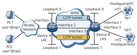
On the network shown in Figure 1, DeviceA and DeviceB function as the LAC and LNS, respectively. The headquarters domain name of enterprise01 is isp1 and PC1 is a user of enterprise01. The headquarters domain name of enterprise02 is isp2 and PC2 is a user of enterprise02. Multiple enterprises share the same LNS, and users of different enterprises need to communicate with their headquarters. The network addresses of the headquarters are private addresses. Generally, users cannot directly access the Intranet server through the Internet. By configuring VPNs and multi-instances, users can access the Intranet data.

In this example, interface1, interface2, and interface3 represent GE 0/1/8, GE 0/1/1, and GE 0/1/16, respectively.
Device |
Interface |
IP Address |
DeviceA |
GigabitEthernet0/1/1.1 |
11.11.11.1/24 |
DeviceA |
GigabitEthernet0/1/8.100 |
- |
DeviceA |
LoopBack0 |
1.1.1.1/32 |
DeviceB |
GigabitEthernet0/1/1.1 |
11.11.11.2/24 |
DeviceB |
GigabitEthernet0/1/8.100 |
- |
DeviceB |
LoopBack0 |
3.3.3.3/32 |
Configuration Roadmap
Addresses of different VPN instances can overlap.
Configure a dial-up connection on the user side.
Configure the LAC.
- Configure the PPPoE access service for the LAC, including configuring a VT and AAA schemes, binding an interface to the VT, and configuring a BAS interface.
- Enable L2TP.
- Configure an L2TP tunnel connection on the LAC side.
- Configure a tunnel authentication mode.
- Configure L2TP user attributes.
- Configure a routing protocol (static routing in this example) to ensure that routes between the LAC and LNS are reachable.
Configure the LNS.
- Create a VPN instance.
- Configure a VT.
- Configure an L2TP tunnel connection on the LNS side.
- Configure a tunnel authentication mode and user authentication mode.
- Configure LNS-side tunnel parameters.
- Configure an address pool for allocating IP addresses to L2TP users and bind the VPN instance to the address pool.
- Configure a domain for L2TP users, specify an address pool for the domain, and bind the VPN instance to the domain.
- Configure a routing protocol (static routing in this example) to ensure that routes between the LAC and LNS are reachable.
- Assign an IP address to the interface connected to the enterprise network and bind the VPN instance to the interface.
Data Preparation
To complete the configuration, you need the following data:
Usernames and passwords of PC1 and PC2
Tunnel password, and the local tunnel name and peer tunnel name on the LNS side
VPN instance name, RD, and RT
Numbers of two VTs and two L2TP groups
IDs, address ranges, and address masks of remote address pools
This section provides only the L2TP-related configuration procedure.
Procedure
- Perform configuration on the user side.
Establish a dial-up network connection, with the access number of DeviceA specified to receive the address assigned by the LNS.
For PC1, enter the username (user1@isp1) and password, which have been registered at the LNS, in the displayed dial-up terminal window.
For PC2, enter the username (user1@isp2) and password, which have been registered at the LNS, in the displayed dial-up terminal window.
- Configure DeviceA (on the LAC side).
# Configure VT1.
<Device> system-view
<~Device> sysname DeviceA
[*Device] commit
[~DeviceA] interface virtual-template 1
[*DeviceA-Virtual-Template1] ppp authentication-mode chap
[*DeviceA-Virtual-Template1] commit
[~DeviceA-Virtual-Template1] quit
# Bind VT1 to GE 0/1/8.100.
[~DeviceA] interface gigabitethernet 0/1/8.100
[*DeviceA-GigabitEthernet0/1/8.100] pppoe-server bind virtual-template 1
[*DeviceA-GigabitEthernet0/1/8.100] commit
[*DeviceA-GigabitEthernet0/1/8.100] user-vlan 1 100
[~DeviceA-GigabitEthernet0/1/8.100-vlan-1-100] quit
# Configure a BAS interface.
[~DeviceA-GigabitEthernet0/1/8.100] bas
[*DeviceA-GigabitEthernet0/1/8.100-bas] access-type layer2-subscriber
[*DeviceA-GigabitEthernet0/1/8.100-bas] authentication-method ppp
[*DeviceA-GigabitEthernet0/1/8.100-bas] commit
[~DeviceA-GigabitEthernet0/1/8.100-bas] quit
[~DeviceA-GigabitEthernet0/1/8.100] quit
# Configure the sub-interface connecting the LAC to the LNS. This sub-interface must be the same as the sub-interface connecting the LNS to the LAC.
[~DeviceA] interface gigabitethernet0/1/1.1
[*DeviceA-GigabitEthernet0/1/1.1] vlan-type dot1q 1
[*DeviceA-GigabitEthernet0/1/1.1] ip address 11.11.11.1 255.255.255.0
[*DeviceA-GigabitEthernet0/1/1.1] commit
[~DeviceA-GigabitEthernet0/1/1.1] quit
# Create a loopback interface.
[~DeviceA] interface loopback0
[*DeviceA-LoopBack0] ip address 1.1.1.1 255.255.255.255
[*DeviceA-LoopBack0] commit
[~DeviceA-LoopBack0] quit
# Configure an L2TP group and specify the related attributes.
[~DeviceA] l2tp enable
[~DeviceA] l2tp-group lac1
[*DeviceA-l2tp-lac1] tunnel name lac1
[*DeviceA-l2tp-lac1] start l2tp ip 3.3.3.3
[*DeviceA-l2tp-lac1] tunnel authentication
[*DeviceA-l2tp-lac1] tunnel password cipher root@123
[*DeviceA-l2tp-lac1] tunnel source loopback0
[*DeviceA-l2tp-lac1] commit
[~DeviceA-l2tp-lac1] quit
# Configure a RADIUS server.
[~DeviceA] radius-server group radius1
[*DeviceA-radius-radius1] radius-server authentication 10.20.20.1 1812
[*DeviceA-radius-radius1] radius-server accounting 10.20.20.1 1813
[*DeviceA-radius-radius1] radius-server shared-key itellin
[*DeviceA-radius-radius1] commit
[~DeviceA-radius-radius1] quit
# Configure user domains.
[~DeviceA] aaa
[*DeviceA-aaa] domain isp1
[*DeviceA-aaa-domain-isp1] l2tp-group lac1
[*DeviceA-aaa-domain-isp1] radius-server group radius1
[*DeviceA-aaa-domain-isp1] authentication-scheme default1
[*DeviceA-aaa-domain-isp1] accounting-scheme default1
[*DeviceA-aaa-domain-isp1] commit
[~DeviceA-aaa-domain-isp1] quit
[~DeviceA-aaa] domain isp2
[*DeviceA-aaa-domain-isp2] l2tp-group lac1
[*DeviceA-aaa-domain-isp2] radius-server group radius1
[*DeviceA-aaa-domain-isp2] authentication-scheme default1
[*DeviceA-aaa-domain-isp2] accounting-scheme default1
[*DeviceA-aaa-domain-isp2] commit
[~DeviceA-aaa-domain-isp2] quit
[~DeviceA-aaa] quit
# Configure a route.
[~DeviceA] ip route-static 3.3.3.3 255.255.255.255 11.11.11.2
- Configure DeviceB (on the LNS side).
# Create two VPN instances.
<Device> system-view
<~Device> sysname DeviceB
[*DeviceB] ip vpn-instance vrf1
[*DeviceB-vpn-instance-vrf1] route-distinguisher 100:1
[*DeviceB-vpn-instance-vrf1] apply-label per-instance
[*DeviceB-vpn-instance-vrf1] vpn-target 100:1 both
[*DeviceB–vpn-instance-vrf1] commit
[~DeviceB–vpn-instance-vrf1] quit
[~DeviceB] ip vpn-instance vrf2
[*DeviceB-vpn-instance-vrf2] route-distinguisher 100:2
[*DeviceB-vpn-instance-vrf2] apply-label per-instance
[*DeviceB-vpn-instance-vrf2] vpn-target 100:2 both
[*DeviceB–vpn-instance-vrf2] commit
[~DeviceB–vpn-instance-vrf2] quit
# Create a sub-interface.
[~DeviceB] interface gigabitethernet0/1/1.1
[*DeviceB-GigabitEthernet0/1/1.1] vlan-type dot1q 1
[*DeviceB-GigabitEthernet0/1/1.1] ip address 11.11.11.2 255.255.255.0
[*DeviceB-GigabitEthernet0/1/1.1] commit
[~DeviceB-GigabitEthernet0/1/1.1] quit
# Create a loopback interface.
[~DeviceB] interface loopback0
[*DeviceB-LoopBack0] ip address 3.3.3.3 255.255.255.255
[*DeviceB-LoopBack0] commit
[~DeviceB-LoopBack0] quit
# Create VT1.
[~DeviceB] interface virtual-template 1
[*DeviceB-Virtual-Template1] ppp authentication-mode chap
[*DeviceB-Virtual-Template1] commit
[~DeviceB-Virtual-Template1] quit
# Enable L2TP and configure an L2TP group.
[~DeviceB] l2tp enable
[~DeviceB] l2tp-group lns1
[*DeviceB-l2tp-lns1] tunnel name lns1
[*DeviceB-l2tp-lns1] allow l2tp virtual-template 1 remote lac1
[*DeviceB-l2tp-lns1] tunnel authentication
[*DeviceB-l2tp-lns1] tunnel password cipher root@123
[*DeviceB-l2tp-lns1] commit
[~DeviceB-l2tp-lns1] quit
# Create and configure the LNS group named group1, and bind the tunnel source interface and tunnel board to the LNS group.
[~DeviceB] lns-group group1
[*DeviceB-lns-group-group1] bind slot 10
[*DeviceB-lns-group-group1] bind source loopback 0
[*DeviceB-lns-group-group1] commit
[~DeviceB-lns-group-group1] quit
# Configure an address pool from which addresses are assigned to users.
[~DeviceB] ip pool pool1 bas local
[*DeviceB-ip-pool-pool1] gateway 10.10.0.1 255.255.255.0
[*DeviceB-ip-pool-pool1] section 0 10.10.0.10 10.10.0.100
[*DeviceB-ip-pool-pool1] vpn-instance vrf1
[*DeviceB-ip-pool-pool1] commit
[~DeviceB-ip-pool-pool1] quit
[~DeviceB] ip pool pool2 bas local
[*DeviceB-ip-pool-pool2] gateway 10.10.0.1 255.255.255.0
[*DeviceB-ip-pool-pool2] section 0 10.10.0.10 10.10.0.100
[*DeviceB-ip-pool-pool2] vpn-instance vrf2
[*DeviceB-ip-pool-pool2] commit
[~DeviceB-ip-pool-pool2] quit
# Configure a RADIUS server.
[~DeviceB] radius-server group radius1
[*DeviceB-radius-radius1] radius-server authentication 10.20.20.1 1812
[*DeviceB-radius-radius1] radius-server accounting 10.20.20.1 1813
[*DeviceB-radius-radius1] radius-server shared-key itellin
[*DeviceB-radius-radius1] commit
[~DeviceB-radius-radius1] quit
# Configure user domains.
[~DeviceB] aaa
[*DeviceB-aaa] domain isp1
[*DeviceB-aaa-domain-isp1] radius-server group radius1
[*DeviceB-aaa-domain-isp1] authentication-scheme default1
[*DeviceB-aaa-domain-isp1] accounting-scheme default1
[*DeviceB-aaa-domain-isp1] ip-pool pool1
[*DeviceB-aaa-domain-isp1] vpn-instance vrf1
[*DeviceB-aaa-domain-isp1] commit
[~DeviceB-aaa-domain-isp1] quit
[~DeviceB-aaa] domain isp2
[*DeviceB-aaa-domain-isp2] radius-server group radius1
[*DeviceB-aaa-domain-isp2] authentication-scheme default1
[*DeviceB-aaa-domain-isp2] accounting-scheme default1
[*DeviceB-aaa-domain-isp2] ip-pool pool2
[*DeviceB-aaa-domain-isp2] vpn-instance vrf2
[*DeviceB-aaa-domain-isp2] commit
[~DeviceB-aaa-domain-isp2] quit
[~DeviceB-aaa] quit
# Configure a route.
[~DeviceB] ip route-static 1.1.1.1 255.255.255.255 11.11.11.1
- Verify the configuration.
[~DeviceA] ping 3.3.3.3
PING 3.3.3.3: 56  data bytes, press CTRL_C to break
    Reply from 3.3.3.3: bytes=56 Sequence=1 ttl=255 time=12 ms
    Reply from 3.3.3.3: bytes=56 Sequence=2 ttl=255 time=10 ms
    Reply from 3.3.3.3: bytes=56 Sequence=3 ttl=255 time=5 ms
    Reply from 3.3.3.3: bytes=56 Sequence=4 ttl=255 time=8 ms

  --- 3.3.3.3 ping statistics ---
    4 packet(s) transmitted
    4 packet(s) received
    0.00% packet loss
    round-trip min/avg/max = 5/8/12 ms

[~DeviceA] test l2tp-tunnel l2tp-group lac1 ip-address 3.3.3.3
Testing L2TP tunnel connectivity now.......
Test L2TP tunnel connectivity success.
# Check that the VPN user can access the headquarters.
PC1 can access Headquarter01 and PC2 can access Headquarter02.
If PC1 enters the username user1@isp2 and the password, PC1 can access Headquarter02 as a user of vrf2.
Configuration Files
DeviceA configuration file
#
 sysname DeviceA
#
 l2tp enable
#
radius-server group radius1
 radius-server authentication 10.20.20.1 1812
 radius-server accounting 10.20.20.1 1813
 radius-server shared-key %^%#vS%796FO7%C~pB%CR=q;j}gSCqR-X6+P!.DYI@)%^%
#
interface Virtual-Template1
 ppp authentication-mode chap
#
interface GigabitEthernet0/1/8
 undo shutdown
#
interface GigabitEthernet0/1/8.100
 pppoe-server bind Virtual-Template 1
 undo shutdown
 user-vlan 1 100
 bas
  access-type layer2-subscriber
#
interface LoopBack0
 ip address 1.1.1.1 255.255.255.255
#
l2tp-group lac1
 tunnel password cipher %@%##!!!!!!!!!"!!!!#!!!!(!!!!JMi&5#;qTW7C9)&16~.M{sv*SzKjgN>0b[,G:tb%!!!!!!!!!!1!!!!E'QA>XV7kJ+tIm3UL=c=%@%#
 tunnel name lac1
 start l2tp ip 3.3.3.3
 tunnel source LoopBack0
#
aaa
domain isp1
  authentication-scheme default1
  accounting-scheme default1
  radius-server group radius1
  l2tp-group lac1
domain isp2
  authentication-scheme default1
  accounting-scheme default1
  radius-server group radius1
  l2tp-group lac1
#
interface GigabitEthernet0/1/1.1
 undo shutdown
 vlan-type dot1q 1
 ip address 11.11.11.1 255.255.255.0
#
 ip route-static 3.3.3.3 255.255.255.255 11.11.11.2
#
return
DeviceB configuration file
#
 sysname DeviceB
#
 l2tp enable
#
radius-server group radius1
 radius-server authentication 10.20.20.1 1812
 radius-server accounting 10.20.20.1 1813
 radius-server shared-key %^%#vS%796FO7%C~pB%CR=q;j}gSCqR-X6+P!.DYI@)%^%
#
interface Virtual-Template1
 ppp authentication-mode chap
#
ip vpn-instance vrf1
 route-distinguisher 100:1
 apply-label per-instance
 vpn-target 100:1 export-extcommunity
 vpn-target 100:1 import-extcommunity
#
ip vpn-instance vrf2
 route-distinguisher 100:2
 apply-label per-instance
 vpn-target 100:2 export-extcommunity
 vpn-target 100:2 import-extcommunity
#
interface LoopBack0
 ip address 3.3.3.3 255.255.255.255
#
l2tp-group lns1
 allow l2tp virtual-template 1 remote lac1
 tunnel password cipher %@%##!!!!!!!!!"!!!!#!!!!(!!!!JMi&5#;qTW7C9)&16~.M{sv*SzKjgN>0b[,G:tb%!!!!!!!!!!1!!!!E'QA>XV7kJ+tIm3UL=c=%@%#
 tunnel name lns1
#
lns-group group1
 bind slot 1
 bind source LoopBack0
#
ip pool pool1 bas local
 vpn-instance vrf1
 gateway 10.10.0.1 255.255.255.0
 section 0 10.10.0.10 10.10.0.100
#
ip pool pool2 bas local
 vpn-instance vrf2
 gateway 10.10.0.1 255.255.255.0
 section 0 10.10.0.10 10.10.0.100
#
aaa
domain  isp1
  authentication-scheme default1
  accounting-scheme default1
  radius-server group radius1
  vpn-instance vrf1
  ip-pool pool1
domain  isp2
  authentication-scheme default1
  accounting-scheme default1
  radius-server group radius1
  vpn-instance vrf2
  ip-pool pool2
#
interface GigabitEthernet0/1/1.1
 undo shutdown
 vlan-type dot1q 1
 ip address 11.11.11.2 255.255.255.0
#
 ip route-static 1.1.1.1 255.255.255.255 11.11.11.1
#
return