Example for Configuring L2TP Session-based QoS Scheduling for User Access
This section provides an example for configuring L2TP session-based QoS scheduling for user access.
Networking Requirements
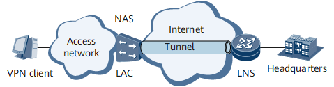
On the network shown in Figure 1, an NetEngine 8000 F functions as the LNS of the L2TP tunnel. A VPN user accesses the company headquarters as follows:
The user dials up to access the Internet.
The NAS authenticates the user and initiates a request for setting up a tunnel to the LNS after finding that the user is a VPN user.
After a tunnel is set up between the NAS and the LNS, the NAS sends packets carrying the content negotiated between the NAS and the VPN user to the LNS.
The LNS determines whether to accept the connection according to pre-negotiated content. In this example, the LNS accepts the connection.
The user communicates with the company headquarters through the tunnel between the NAS and the LNS.
The user accesses the network using the domain doma1 and obtains the IP address from the address pool pool1.
It is required that session-based L2TP QoS scheduling be configured for the LNS to ensure that:
Each user in the domain uses CIR 10 Mbit/s and PIR 20 Mbit/s.
All users on the L2TP tunnel share PIR 100 Mbit/s.
Configuration Roadmap
The configuration roadmap is as follows:
Configure the LAC.
Configure the LNS.
Configure a scheduling profile and a QoS profile.
Apply the QoS profile to the domain.
Configure session-based L2TP QoS scheduling for an L2TP group.
Data Preparation
To complete the configuration, you need the following data:
Loopback address
Name, network segment, and gateway of the address pool
Name of a user access domain
Names of the scheduling profile and QoS profile
Procedure
- Configure a dial-up connection on the user side.
Enter vpdnuser@doma1 as the VPN username, 1qaz@WSX as the password, and 170 as the dial-in number in the dial-up window to dial in. In the displayed dialog box, enter username as the username and Userpass0 as the password for RADIUS authentication.
- Configure the LAC.
The NAS functions as the LAC.
# Configure 170 as the dial-in number on the NAS.
# Create a VPN user on the RADIUS server with username username and password Userpass0, and configure the IP address of the LNS (192.168.0.1).
# Set the local device name to lac and perform tunnel authentication with the tunnel authentication password being 1qaz#EDC.
- Configure the LNS (NetEngine 8000 F).
# Create a virtual template and configure a PPP authentication mode for it.
<Device> system-view
[~Device] interface virtual-template 1
[*Device-Virtual-Template1] ppp authentication-mode chap
[*Device-Virtual-Template1] commit
[~Device-Virtual-Template1] quit
# Enable L2TP and configure an L2TP group.
[~Device] l2tp enable
[*Device] commit
[~Device] l2tp-group lns1
# Set the L2TP group to the LNS type, bind it to the virtual template, and specify the LAC tunnel name for the L2TP group.
[*Device-l2tp-lns1] tunnel name LNS
[*Device-l2tp-lns1] allow l2tp virtual-template 1 remote lac
# Configure tunnel authentication and set a password for tunnel authentication.
[*Device-l2tp-lns1] tunnel authentication
[*Device-l2tp-lns1] tunnel password cipher root@123
[*Device-l2tp-lns1] commit
[~Device-l2tp-lns1] quit
# Configure an address pool to allocate an IP address to the dial-in user.
[~Device] ip pool pool1 bas local
[*Device-ip-pool-pool1] gateway 10.10.10.1 255.255.255.0
[*Device-ip-pool-pool1] section 0 10.10.10.2 10.10.10.100
[*Device-ip-pool-pool1] commit
[~Device-ip-pool-pool1] quit
# Configure a RADIUS server group.
[~Device] radius-server group radius1
[*Device-radius-radius1] radius-server authentication 10.20.20.1 1812
[*Device-radius-radius1] radius-server accounting 10.20.20.1 1813
[*Device-radius-radius1] radius-server shared-key itellin
[*Device-radius-radius1] commit
[~Device-radius-radius1] quit
# Configure a domain named doma1.
[~Device] aaa
[*Device-aaa] domain doma1
[*Device-aaa-domain-domain1]radius-server group radius1
[*Device-aaa-domain-doma1] authentication-scheme default1
[*Device-aaa-domain-doma1] accounting-scheme default1
[*Device-aaa-domain-doma1] ip-pool pool1
[*Device-aaa-domain-doma1] commit
[~Device-aaa-domain-doma1] quit
[~Device-aaa] quit
# Create a loopback interface.
[~Device] interface loopback 0
[*Device-LoopBack0] ip address 192.168.0.1 255.255.255.255
[*Device-LoopBack0] commit
[~Device-LoopBack0] quit
# Create an LNS group named group1.
[~Device] lns-group group1
# Bind the tunnel board in slot 1 to the LNS group.
[*Device-lns-group-group1] bind slot 1
# Bind loopback 0 to the LNS group.
[*Device-lns-group-group1] bind source loopback 0
[*Device-lns-group-group1] commit
[~Device-lns-group-group1] quit
- Configure a QoS profile and a scheduling profile.
[~Device] qos-profile pro1
[*Device-qos-pro1] user-queue cir 10000 pir 20000 inbound
[*Device-qos-pro1] user-queue cir 10000 pir 20000 outbound
[*Device-qos-pro1] commit
[~Device-qos-pro1] quit
[~Device] user-group-queue pro2 slot 1
[*Device-user-group-queue-pro2-slot-1] shaping 100000 inbound
[*Device-user-group-queue-pro2-slot-1] commit
[~Device-user-group-queue-pro2-slot-1] quit
- Apply the QoS profile to the domain.
[~Device] aaa
[*Device-aaa] domain doma1
[*Device-aaa-domain-doma1] qos-profile pro1 inbound lns-gts
[*Device-aaa-domain-doma1] commit
[~Device-aaa-domain-doma1] quit
[~Device-aaa] quit
- Set session-based QoS scheduling for the L2TP group, and apply the scheduling profile to the L2TP group.
[~Device] l2tp-group lns1
[*Device-l2tp-lns1] qos scheduling-mode session
[*Device-l2tp-lns1] user-group-queue pro2 inbound
[*Device-l2tp-lns1] commit
[~Device-l2tp-lns1] quit
- Verify the configuration.
Run the display l2tp-group command to check the scheduling mode configured for the L2TP group.
<Device> display l2tp-group lns1
 -----------------------------------------------
 L2tp-index      : 3
 Group-Name      : lns1
 .........
 QOS-mode        : session
.........
 -----------------------------------------------
Run the display domain command to check the QoS profile configured for the L2TP group.
<Device> display domain doma1
 ------------------------------------------------------------------------------
  Domain-name                     : doma1
  Domain-state                    : Active
...............
  L2TP-QosProfile-inbound         : pro1
...............
  ------------------------------------------------------------------------------
Configuration Files
#
 sysname Device
#
 l2tp enable
#
radius-server group radius1
 radius-server authentication 10.20.20.1 1812
 radius-server accounting 10.20.20.1 1813
 radius-server shared-key %^%#vS%796FO7%C~pB%CR=q;j}gSCqR-X6+P!.DYI@)%^%
#
qos-profile pro1
 user-queue cir 10000 pir 20000 inbound
 user-queue cir 10000 pir 20000 outbound
#
user-group-queue pro2
 shaping 100000 inbound
#
interface Virtual-Template1
 ppp authentication-mode chap
#
interface GigabitEthernet0/1/0
 undo shutdown
#
interface GigabitEthernet0/1/0.2
 pppoe-server bind Virtual-Template 1
 user-vlan 270 277
 undo shutdown
 bas
  access-type layer2-subscriber
#
interface LoopBack0
 ip address 192.168.0.1 255.255.255.255
#
l2tp-group lns1
 allow l2tp virtual-template 1 remote lac
 tunnel password cipher %@%##!!!!!!!!!"!!!!"!!!!(!!!!1];16qfZ81fv"uMoKKZ.1k"`AO!X2K2N.b~'NB^V!!!!!!!!!!1!!!!o/4J(q"J1F.!K9%M!6x8%@%#
 tunnel name LNS
 qos scheduling-mode session
 user-group-queue pro2 inbound
#
lns-group group1
 bind slot 1
 bind source LoopBack0
#
ip pool pool1 bas local
 gateway 10.10.10.1 255.255.255.0
 section 0 10.10.10.2 10.10.10.100
#
aaa
 domain  doma1
  radius-server group  radius1
  authentication-scheme   default1
  accounting-scheme   default1
  ip-pool   pool1
  qos-profile pro1 inbound lns-gts
#
return