Example for Configuring the Internal Server Through 1:1 NAT (Traffic Diversion on an Inbound Interface)
This section provides an example for configuring the internal server through 1:1 NAT. By specifying an internal NAT server and configuring the mapping entries between the internal server's private IP address/port and public IP address/port, an external host can access the internal server.
Networking Requirements
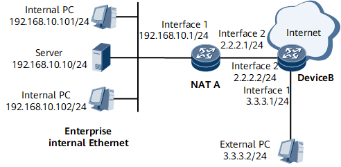
In Figure 1, the router performs the NAT function to help PCs within the enterprise network access the Internet. The router uses GE 0/1/1 to connect to an internal network and GE 0/1/2 to connect to the Internet.
The internal network address of the enterprise network is 192.168.0.0/16. The internal server address is 192.168.10.10/24. Only PCs on the network segment of 192.168.10.0/24 can access the Internet. External PCs can access the internal server. The enterprise has five valid IP addresses ranging from 1.1.1.101/24 to 1.1.1.105/24. The internal server of the enterprise has an independent public address 1.1.1.100. The internal server can be accessed from the external network address 3.3.3.2 through 1:1 NAT.
Configuration Roadmap
- Configure basic functions of NAT.
- Configure a NAT traffic diversion policy.
- Configure an internal NAT server.
Data Preparation
Service-location group index: 1
Service-instance group name: group1
NAT instance name: nat1; NAT instance index: 1
NAT address pool name for NATA: address-group1; NAT address pool ID: 1; IP address segment: 1.1.1.101 to 1.1.1.105
ACL number: 3001
Traffic classifier name: classifier1
Traffic behavior name: behavior1
Traffic policy name: policy1
Number and IP address of the interface that applies the NAT traffic policy: GE 0/1/1, 192.168.10.1/24
Private IP address of the internal NAT server: 192.168.10.10; public IP address of the internal NAT server: 1.1.1.100
Procedure
- Configure basic functions of NAT.
- Configure a NAT traffic diversion policy.Apply a NAT traffic diversion policy on either an inbound or outbound interface as required.

A NAT traffic diversion policy on an inbound and that on an outbound interface are mutually exclusive on a device.
- Apply the NAT traffic diversion policy to the inbound interface.
- Configure traffic classification rules based on ACL 3001.
Rule 1: Only PCs with the internal network segment address as 192.168.10.0/24 can access the Internet.
[~NATA] acl 3001
[*NATA-acl4-advance-3001] rule 1 permit ip source 192.168.10.0 0.0.0.255
[*NATA-acl4-advance-3001] commit
[~NATA-acl4-advance-3001] quit
- Configure a traffic classifier named classifier1 and define an ACL-based matching rule.
[~NATA] traffic classifier classifier1
[*NATA-classifier-classifier1] if-match acl 3001
[*NATA-classifier-classifier1] commit
[~NATA-classifier-classifier1] quit
- Configure a traffic behavior named behavior1 and bind it to the NAT instance.
[~NATA] traffic behavior behavior1
[*NATA-behavior-behavior1] nat bind instance nat1
[*NATA-behavior-behavior1] commit
[~NATA-behavior-behavior1] quit
- Define a NAT traffic policy named policy1 to associate the ACL rule with the traffic behavior.
[~NATA] traffic policy policy1
[*NATA-trafficpolicy-policy1] classifier classifier1 behavior behavior1
[*NATA-trafficpolicy-policy1] commit
[~NATA-trafficpolicy-policy1] quit
- Apply the NAT traffic policy in the interface view.
[~NATA] interface gigabitEthernet 0/1/1
[~NATA-GigabitEthernet0/1/1] ip address 192.168.10.1 24
[*NATA-GigabitEthernet0/1/1] traffic-policy policy1 inbound
[*NATA-GigabitEthernet0/1/1] commit
[~NATA-GigabitEthernet0/1/1] quit
- Configure the IP address of GE 0/1/2.
[~NATA] interface gigabitEthernet 0/1/2
[*NATA-GigabitEthernet0/1/2] ip address 2.2.2.1 24
[*NATA-GigabitEthernet0/1/2] commit
[~NATA-GigabitEthernet0/1/2] quit
- Configure traffic classification rules based on ACL 3001.
- Apply the NAT traffic diversion policy to the outbound interface.
- Configure traffic classification rules based on ACL 3001.
Rule 1: Only PCs with the internal network segment address as 192.168.10.0/24 can access the Internet.
[~NATA] acl 3001
[*NATA-acl4-advance-3001] rule 1 permit ip source 192.168.10.0 0.0.0.255
[*NATA-acl4-advance-3001] commit
[~NATA-acl4-advance-3001] quit
- Apply the NAT traffic policy in the interface view.
[~NATA] interface gigabitEthernet 0/1/2
[~NATA-GigabitEthernet0/1/2] ip address 2.2.2.1 24
[*NATA-GigabitEthernet0/1/2] nat bind acl 3001 instance nat1
[*NATA-GigabitEthernet0/1/2] commit
[~NATA-GigabitEthernet0/1/2] quit
- Configure the IP address of GE 0/1/1
[~NATA] interface gigabitEthernet 0/1/1
[*NATA-GigabitEthernet0/1/1] ip address 192.168.10.1 24
[*NATA-GigabitEthernet0/1/1] commit
[~NATA-GigabitEthernet0/1/1] quit
- Configure traffic classification rules based on ACL 3001.
- Apply the NAT traffic diversion policy to the inbound interface.
- Define the internal server address as 192.168.10.10 and external address as 1.1.1.100. Use the address-level mode to ensure 1:1 relationship between the public and private IP addresses.
[~NATA] nat instance nat1
[~NATA-nat-instance-nat1] nat server-mode enable
[~NATA-nat-instance-nat1] nat server global 1.1.1.100 inside 192.168.10.10
[*NATA-nat-instance-nat1] commit
[~NATA-nat-instance-nat1] quit
- Configure a default route as a static route and set the next hop address of the default route to 2.2.2.2.
[~NATA] ip route-static 0.0.0.0 0.0.0.0 2.2.2.2
[*NATA] commit
- Verify the configuration.
# View server mapping entries of all users.
<NATA> display nat server-map
This operation will take a few minutes. Press 'Ctrl+C' to break ...
Slot: 1
Total number:  2.
  NAT Instance: nat1
  Protocol:ANY, VPN:--->-
  Server:192.168.10.10[1.1.1.100]->ANY
  Tag:0x0, TTL:-, Left-Time:-
  CPE IP:192.168.10.10
  NAT Instance: nat1
  Protocol:ANY, VPN:--->-
  Server reverse:ANY->1.1.1.100[192.168.10.10]
  Tag:0x0, TTL:-, Left-Time:-
  CPE IP:192.168.10.10
Configuration Files
NATA configuration file when a NAT traffic diversion policy is used on an inbound interface
#
 sysname NATA
#
service-location 1
 location slot 1
#
service-instance-group group1
 service-location 1
#
nat instance nat1 id 1
 service-instance-group group1
 nat address-group address-group1 group-id 1 1.1.1.101 1.1.1.105
 nat server-mode enable
 nat server global 1.1.1.100 inside 192.168.10.10
#
acl number 3001
 rule 1 permit ip source 192.168.10.0 0.0.0.255
#
traffic classifier classifier1 operator or
 if-match acl 3001
#
traffic behavior behavior1
 nat bind instance nat1
#
traffic policy policy1
 classifier classifier1 behavior behavior1 precedence 1
#
interface GigabitEthernet 0/1/1
 undo shutdown
 ip address 192.168.10.1 255.255.255.0
 traffic-policy policy1 inbound
#
interface GigabitEthernet 0/1/2
 undo shutdown
 ip address 2.2.2.1 255.255.255.0
#
ospf 1
 area 0.0.0.0
  network 2.2.2.0 0.0.0.255
#
ip route-static 0.0.0.0 0.0.0.0 2.2.2.2
#
 return
NATA configuration file when a NAT traffic diversion policy is used on an outbound interface
#
 sysname NATA
#
service-location 1
 location slot 1
#
service-instance-group group1
 service-location 1
#
nat instance nat1 id 1
 service-instance-group group1
 nat address-group address-group1 group-id 1 1.1.1.101 1.1.1.105
 nat server-mode enable
 nat server global 1.1.1.100 inside 192.168.10.10
#
acl number 3001
 rule 1 permit ip source 192.168.10.0 0.0.0.255
#
interface GigabitEthernet 0/1/1
 undo shutdown
 ip address 192.168.10.1 255.255.255.0
#
interface GigabitEthernet 0/1/2
 undo shutdown
 ip address 2.2.2.1 255.255.255.0
 nat bind acl 3001 instance nat1
#
ospf 1
 area 0.0.0.0
  network 2.2.2.0 0.0.0.255
#
ip route-static 0.0.0.0 0.0.0.0 2.2.2.2
#
 return
Device B configuration file
#
 sysname DeviceB
#
interface GigabitEthernet 0/1/1
 undo shutdown
 ip address 3.3.3.1 255.255.255.0
#
interface GigabitEthernet 0/1/3
 undo shutdown
 ip address 2.2.2.2 255.255.255.0
#
ospf 1
 area 0.0.0.0
  network 2.2.2.0 0.0.0.255
  network 3.3.3.0 0.0.0.255
#
 return