This section provides an example for configuring NAT easy IP on an outbound interface and the hairpin function. The function combination allows internal hosts to access the Internet through the outbound NAT function and to access an internal server that is created using the easy IP function.
Networking Requirements
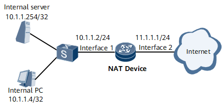
In Figure 1, a host on a private network is connected to the Internet through the router on which NAT traffic distribution on an outbound interface is configured. The host uses a public IP address to access an internal server that is created in Easy IP mode on the same NAT device. The router is connected to the private network through 0/1/9. The router's GE 0/1/10 is connected to the Internet. The public IP addresses 11.1.1.2/32 and 11.1.1.3/32 are available.
Figure 1 shows IP addresses of interfaces. The configuration requirements are as follows:
- PCs on the private network segment of 10.1.1.4/32 can access the Internet.
- PCs on the private network segment of 10.1.1.4/32 can access the internal server using a public IP address.
- The host uses a public IP address to access an internal server that is created in Easy IP mode on the same NAT device.
Figure 1 Scenario in which NAT traffic distribution on an outbound interface, easy IP, and the hairpin function are configured
Interfaces 1 and 2 in this example represent GE 0/1/9 and GE 0/1/10, respectively.
Configuration Roadmap
The configuration roadmap is as follows:
- Configure a NAT instance.
- Configure an internal server in Easy IP mode.
- Bind an outbound interface to the NAT instance.
Data Preparation
To complete the configuration, you need the following data:
NAT instance name (nat1) and index (1)
NAT Device's NAT address pool name (address-group1), address pool number (1), a range of public IP addresses (11.1.1.2 and 11.1.1.3)
ACL number (3001) to match traffic that a private network host sends to the Internet
ACL number (3001) to match traffic that a private network host sends to the private network server
Name and IP address of each interface to which a NAT traffic diversion policy is applied
Procedure
- Configure basic NAT functions.
- Configure a NAT instance named nat1.
[~NAT Device] service-location 1
[*NAT Device-service-location-1] location slot 1
[*NAT Device-service-location-1] commit
[~NAT Device-service-location-1] quit
[~NAT Device] service-instance-group group1
[*NAT Device-service-instance-group-group1] service-location 1
[*NAT Device-service-instance-group-group1] commit
[~NAT Device-service-instance-group-group1] quit
[~NAT Device] nat instance nat1 id 1
[*NAT Device-nat-instance-nat1] service-instance-group group1
[*NAT Device-nat-instance-nat1] commit
[~NAT Device-nat-instance-nat1] quit
- Configure a NAT address pool and specify a range of IP addresses 11.1.1.2 to 11.1.1.3 in the pool.
[~NAT Device] nat instance nat1
[~NAT Device-nat-instance-nat1] nat address-group address-group1 group-id 1 11.1.1.2 11.1.1.3
[*NAT Device-nat-instance-nat1] commit
[~NAT Device-nat-instance-nat1] quit
- Configure an internal server in Easy IP mode.
- Configure the public network interface.
[~NAT Device] interface gigabitEthernet 0/1/10
[~NAT Device-GigabitEthernet0/1/10] ip address 11.1.1.1 255.255.255.0
[*NAT Device-GigabitEthernet0/1/10] commit
[~NAT Device-GigabitEthernet0/1/10] quit
- Configure an internal server and the public IP address of the server to reuse the IP address of interface 0/1/10. In this example, TCP port 80 is used on an internal server.
[~NAT Device] nat instance nat1
[~NAT Device-nat-instance-nat1] nat server protocol tcp global unnumbered interface GigabitEthernet0/1/10 80 inside 10.1.1.254 80
[*NAT Device-nat-instance-nat1] commit
[~NAT Device-nat-instance-nat1] quit
- Configure a NAT traffic diversion policy on an outbound interface.
- Configure an ACL to allow the PC with the internal IP address 10.1.1.4/32 to access the Internet and communicate with the internal server.
[~NAT Device] acl 3001
[*NAT Device-acl4-advance-3001] rule 1 permit ip source 10.1.1.4 0.0.0.0
[*NAT Device-acl4-advance-3001] rule 2 permit tcp source 10.1.1.254 0.0.0.0
[*NAT Device-acl4-advance-3001] commit
[~NAT Device-acl4-advance-3001] quit
- Configure a NAT diversion policy on the public network outbound interface.
[~NAT Device] interface gigabitEthernet 0/1/10
[*NAT Device-GigabitEthernet0/1/10] nat bind acl 3001 instance nat1
[*NAT Device-GigabitEthernet0/1/10] commit
[~NAT Device-GigabitEthernet0/1/10] quit
- Configure a NAT diversion policy on the private network outbound interface.
[~NAT Device] interface gigabitEthernet 0/1/9
[*NAT Device-GigabitEthernet0/1/9] ip address 10.1.1.2 255.255.255.0
[*NAT Device-GigabitEthernet0/1/9] nat bind acl 3001 instance nat1
[*NAT Device-GigabitEthernet0/1/9] commit
[~NAT Device-GigabitEthernet0/1/9] quit
Configuration File
#
sysname NAT Device
#
service-location 1
 location slot 1
#
service-instance-group group1
 service-location 1
#
acl number 3001
 rule 1 permit ip source 10.1.1.4 0.0.0.0
 rule 2 permit tcp source 10.1.1.254 0.0.0.0
#
nat instance nat1 id 1
 service-instance-group group1
 nat address-group address-group1 group-id 1 11.1.1.2 11.1.1.3
 nat server protocol tcp global unnumbered interface GigabitEthernet0/1/10 80 inside 10.1.1.254 80
#
interface gigabitEthernet 0/1/9
 undo shutdown
 ip address 10.1.1.2 255.255.255.0
 nat bind acl 3001 instance nat1
#
interface gigabitEthernet 0/1/10
 undo shutdown
 ip address 11.1.1.1 255.255.255.0
 nat bind acl 3001 instance nat1
#
return