Example for Configuring Priority Mappings Based on Simple Traffic Classification (MPLS)
This part describes how to configure simple traffic classification in the context of priority mappings for MPLS packets.
Networking Requirements
MPLS neighbor relationships are established between DeviceA, DeviceB, and DeviceC. When IP packets reach DeviceA, DeviceA adds MPLS header to these IP packets before transmitting them to DeviceC. When these MPLS packets reach DeviceC, DeviceC removes their MPLS headers and forwards them as IP packets.
In this manner, the DSCP value of the IP traffic can be changed to the EXP value of MPLS traffic on DeviceA, and the EXP value of MPLS traffic can be changed to the DSCP value of the IP traffic on DeviceC.
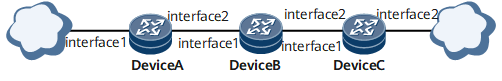

In this configuration example, it is assumed that the three routers have been configured so that DeviceA forwards IP traffic as MPLS traffic to DeviceC, and Deviceforwards MPLS traffic as IP traffic.
This example lists only the commands related to QoS.
- Interfaces 1 through 2 in this example are GE 0/1/0, GE 0/1/8, respectively.
Configuration Roadmap
The configuration roadmap is as follows:
On the inbound interface GigabitEthernet 0/1/0 of DeviceA, configure the mapping from the IP DSCP field to the MPLS EXP field and enable simple traffic classification.
On the inbound interface GigabitEthernet 0/1/0 of DeviceC, configure the mapping from the MPLS EXP field to the IP DSCP field and enable simple traffic classification.
Data Preparation
To complete the configuration, you need the following data:
MPLS EXP values, the internal service classes and colors of the packets on the router, and the DSCP values of IP packets to be mapped
Procedure
- Configure basic MPLS functions and routes (detail omitted here).
For detailed configuration, refer to the HUAWEI NetEngine 8000 F SeriesRouter Configuration Guide - MPLS.
- Configure the mapping between DSCP field and EXP field at GigabitEthernet0/1/0 on DeviceA.
[~DeviceA] diffserv domain default
[*DeviceA-dsdomain-default] ip-dscp-inbound 18 phb af4 green
[*DeviceA-dsdomain-default] mpls-exp-outbound af4 green map 5
[*DeviceA-dsdomain-default] commit
[~DeviceA-dsdomain-default] quit
[~DeviceA] interface GigabitEthernet 0/1/0
[~DeviceA-GigabitEthernet0/1/0] undo shutdown
[*DeviceA-GigabitEthernet0/1/0] trust upstream default
[*DeviceA-GigabitEthernet0/1/0] commit
[~DeviceA-GigabitEthernet0/1/0] quit
[~DeviceA] interface GigabitEthernet 0/1/8
[~DeviceA-GigabitEthernet0/1/8] undo shutdown
[*DeviceA-GigabitEthernet0/1/8] trust upstream default
[*DeviceA-GigabitEthernet0/1/8] commit
[~DeviceA-GigabitEthernet0/1/8] quit
In the preceding configuration, AF2 green packets (DSCP value being 18) are mapped to the internal service level of AF4 of the router on the inbound interface of DeviceA. On the outbound interface, the internal service level of AF4 of the router is mapped to the EF service level (MPLS priority 5) of the MPLS service. In this manner, the traffic that enters DeviceA leaves as EF traffic.
- Configure the mapping from the MPLS EXP field to the IP DSCP field on GigabitEthernet 0/1/0 of DeviceC.
[~DeviceC] diffserv domain default
[*DeviceC-dsdomain-default] mpls-exp-inbound 5 phb af3 green
[*DeviceC-dsdomain-default] ip-dscp-outbound af3 green map 32
[*DeviceC-dsdomain-default] commit
[~DeviceC-dsdomain-default] quit
[~DeviceC] interface GigabitEthernet 0/1/0
[~DeviceC-GigabitEthernet0/1/0] undo shutdown
[*DeviceC-GigabitEthernet0/1/0] trust upstream default
[*DeviceC-GigabitEthernet0/1/0] commit
[~DeviceC-GigabitEthernet0/1/0] quit
[~DeviceC] interface GigabitEthernet 0/1/8
[~DeviceC-GigabitEthernet0/1/8] undo shutdown
[*DeviceC-GigabitEthernet0/1/8] trust upstream default
[*DeviceC-GigabitEthernet0/1/8] commit
[~DeviceC-GigabitEthernet0/1/8] quit
In the preceding configuration, the MPLS priority 5 is mapped to the internal service level of AF3 (green packets) of the router on the inbound interface of DeviceC. On the outbound interface, the internal service level of AF3 (green packets) of the router is mapped to the DSCP value of 32. In this manner, the traffic that enters DeviceC leaves as AF4 traffic.
- Verify the configuration.
After the preceding configurations, if traffic is sent from GigabitEthernet 0/1/0 on DeviceA at 100 Mbit/s with the DSCP value being 18, DeviceC forwards the traffic at 100 Mbit/s with the DSCP value being 32.
Configuration Files
Configuration file of DeviceA
#
 sysname DeviceA
#
diffserv domain default
  ip-dscp-inbound 18 phb af4 green
  mpls-exp-outbound af4 green map 5
#
interface GigabitEthernet0/1/0
 undo shutdown
 ip address 2.2.2.1 255.255.255.0
 trust upstream default
#
interface GigabitEthernet0/1/8
 undo shutdown
 ip address 3.3.3.1 255.255.255.0
 trust upstream default
#
return
Configuration file of DeviceC
#
 sysname DeviceC
#
diffserv domain default
  ip-dscp-outbound af3 green map 32
  mpls-exp-inbound 5 phb af3 green
#
interface GigabitEthernet0/1/0
 undo shutdown
 ip address 4.4.4.1 255.255.255.0
 trust upstream default
#
interface GigabitEthernet0/1/8
 undo shutdown
 ip address 5.5.5.1 255.255.255.0
 trust upstream default
#
return