Example for Configuring CBTS in a VLL over TE Scenario
Networking Requirements
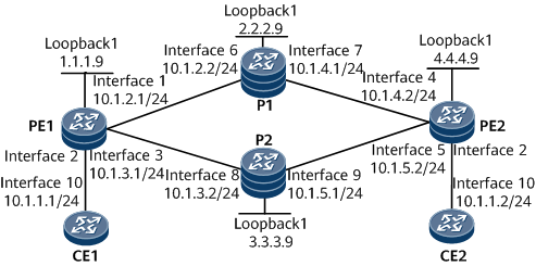
In Figure 1, CE1 and CE2 belong to the same VLL network. They access the MPLS backbone network through PE1 and PE2, respectively. OSPF is used as an IGP on the MPLS backbone network.
It is required that an LDP VLL and the dynamic signaling protocol RSVP-TE be used to establish two MPLS TE tunnels between PE1 and PE2 to transmit VLL services. Each TE tunnel is assigned a specific priority. Interfaces that receive VLL packets have behavior aggregate classification enabled and trust 8021.p priority values so that they can forward VLL packets with a specific priority to a specific tunnel.
TE1 tunnel with ID 100 is established over the path PE1 –> P1 –> PE2, and TE2 tunnel with ID 200 is established over the path PE1 –> P2 –> PE2. AF1 is configured on TE1 interface, and AF2 is configured on TE2 interface. This configuration allows PE1 to forward traffic with service class AF1 along TE1 tunnel and traffic with service class AF2 along TE2 tunnel. The two tunnels can load-balance traffic based on priority values. The requirements on PE2 are similar to those on PE1.
Note that if multiple tunnels with AF1 are established between PE1 and PE2, packets mapped to AF1 are load-balanced along these tunnels.

When CBTS is configured, do not configure the following services:
- Dynamic load balancing

Configuration Roadmap
The configuration roadmap is as follows:
Enable an IGP on the MPLS backbone network for devices on the backbone network to communicate.
Establish MPLS TE tunnels and configure a tunnel policy. For details about how to configure an MPLS TE tunnel, see "MPLS TE Configuration" in HUAWEI NetEngine 8000 F Series Router Configuration Guide - MPLS.
Enable MPLS Layer 2 virtual private network (L2VPN) on the PEs.
Create a VLL, configure LDP as a signaling protocol, and bind the VLL to an AC interface on each PE.
Configure MPLS TE tunnels to transmit VLL packets.
Data Preparation
To complete the configuration, you need the following data:
OSPF area enabled with TE
VLL name and VLL ID
IP addresses of peers and tunnel policy
Name of AC interfaces bound to a VLL
Interface number and IP address of each tunnel interface, as well as destination IP address, tunnel ID, tunnel signaling protocol (RSVP-TE), and tunnel bandwidth to be specified on each tunnel interface
Procedure
- Assign an IP address to each interface.
Configure the IP address and mask for each interface according to Figure 1.
- Enable MPLS, MPLS TE, MPLS RSVP-TE, and MPLS CSPF.
On the nodes along each MPLS TE tunnel, enable MPLS, MPLS TE, and MPLS RSVP-TE both in the system view and the interface view. On the ingress node of each tunnel, enable MPLS CSPF in the system view.
# Configure PE1.
[~PE1] mpls lsr-id 1.1.1.9
[*PE1] mpls
[*PE1-mpls] mpls te
[*PE1-mpls] mpls rsvp-te
[*PE1-mpls] mpls te cspf
[*PE1-mpls] quit
[*PE1] interface gigabitethernet0/1/9
[*PE1-GigabitEthernet0/1/9] mpls
[*PE1-GigabitEthernet0/1/9] mpls te
[*PE1-GigabitEthernet0/1/9] mpls rsvp-te
[*PE1-GigabitEthernet0/1/9] quit
[*PE1] commit
[*PE1] interface gigabitethernet0/1/11
[*PE1-GigabitEthernet0/1/11] mpls
[*PE1-GigabitEthernet0/1/11] mpls te
[*PE1-GigabitEthernet0/1/11] mpls rsvp-te
[*PE1-GigabitEthernet0/1/11] quit
[*PE1] commit
# Configure P1.
[~P1] mpls lsr-id 2.2.2.9
[*P1] mpls
[*P1-mpls] mpls te
[*P1-mpls] mpls rsvp-te
[*P1-mpls] quit
[*P1] interface gigabitethernet0/1/17
[*P1-GigabitEthernet0/1/17] mpls
[*P1-GigabitEthernet0/1/17] mpls te
[*P1-GigabitEthernet0/1/17] mpls rsvp-te
[*P1-GigabitEthernet0/1/17] quit
[*P1] interface gigabitethernet0/1/25
[*P1-GigabitEthernet0/1/25] mpls
[*P1-GigabitEthernet0/1/25] mpls te
[*P1-GigabitEthernet0/1/25] mpls rsvp-te
[*P1-GigabitEthernet0/1/25] quit
[*P1] commit
# Configure P2.
[~P2] mpls lsr-id 3.3.3.9
[*P2] mpls
[*P2-mpls] mpls te
[*P2-mpls] mpls rsvp-te
[*P2-mpls] quit
[*P2] interface gigabitethernet0/1/24
[*P2-GigabitEthernet0/1/24] mpls
[*P2-GigabitEthernet0/1/24] mpls te
[*P2-GigabitEthernet0/1/24] mpls rsvp-te
[*P2-GigabitEthernet0/1/24] quit
[*P2] interface gigabitethernet0/1/19
[*P2-GigabitEthernet0/1/19] mpls
[*P2-GigabitEthernet0/1/19] mpls te
[*P2-GigabitEthernet0/1/19] mpls rsvp-te
[*P2-GigabitEthernet0/1/19] quit
[*P2] commit
# Configure PE2.
[~PE2] mpls lsr-id 4.4.4.9
[*PE2] mpls
[*PE2-mpls] mpls te
[*PE2-mpls] mpls rsvp-te
[*PE2-mpls] mpls te cspf
[*PE2-mpls] quit
[*PE2] interface gigabitethernet0/1/33
[*PE2-GigabitEthernet0/1/33] mpls
[*PE2-GigabitEthernet0/1/33] mpls te
[*PE2-GigabitEthernet0/1/33] mpls rsvp-te
[*PE2-GigabitEthernet0/1/33] quit
[*PE2] commit
[*PE2] interface gigabitethernet0/1/32
[*PE2-GigabitEthernet0/1/32] mpls
[*PE2-GigabitEthernet0/1/32] mpls te
[*PE2-GigabitEthernet0/1/32] mpls rsvp-te
[*PE2-GigabitEthernet0/1/32] quit
[*PE2] commit
- Enable OSPF and OSPF TE on the MPLS backbone network.
# Configure PE1.
[~PE1] ospf
[*PE1-ospf-1] opaque-capability enable
[*PE1-ospf-1] area 0.0.0.0
[*PE1-ospf-1-area-0.0.0.0] network 1.1.1.9 0.0.0.0
[*PE1-ospf-1-area-0.0.0.0] network 10.1.2.0 0.0.0.255
[*PE1-ospf-1-area-0.0.0.0] network 10.1.3.0 0.0.0.255
[*PE1-ospf-1-area-0.0.0.0] mpls-te enable
[*PE1-ospf-1-area-0.0.0.0] quit
[*PE1-ospf-1] quit
[*PE1] commit
# Configure P1.
[~P1] ospf
[*P1-ospf-1] opaque-capability enable
[*P1-ospf-1] area 0.0.0.0
[*P1-ospf-1-area-0.0.0.0] network 2.2.2.9 0.0.0.0
[*P1-ospf-1-area-0.0.0.0] network 10.1.4.0 0.0.0.255
[*P1-ospf-1-area-0.0.0.0] network 10.1.2.0 0.0.0.255
[*P1-ospf-1-area-0.0.0.0] mpls-te enable
[*P1-ospf-1-area-0.0.0.0] quit
[*P1-ospf-1] quit
[*P1] commit
# Configure P2.
[~P2] ospf
[*P2-ospf-1] opaque-capability enable
[*P2-ospf-1] area 0.0.0.0
[*P2-ospf-1-area-0.0.0.0] network 3.3.3.9 0.0.0.0
[*P2-ospf-1-area-0.0.0.0] network 10.1.3.0 0.0.0.255
[*P2-ospf-1-area-0.0.0.0] network 10.1.5.0 0.0.0.255
[*P2-ospf-1-area-0.0.0.0] mpls-te enable
[*P2-ospf-1-area-0.0.0.0] quit
[*P2-ospf-1] quit
[*P2] commit
# Configure PE2.
[~PE2] ospf
[*PE2-ospf-1] opaque-capability enable
[*PE2-ospf-1] area 0.0.0.0
[*PE2-ospf-1-area-0.0.0.0] network 4.4.4.9 0.0.0.0
[*PE2-ospf-1-area-0.0.0.0] network 10.1.4.0 0.0.0.255
[*PE2-ospf-1-area-0.0.0.0] network 10.1.5.0 0.0.0.255
[*PE2-ospf-1-area-0.0.0.0] mpls-te enable
[*PE2-ospf-1-area-0.0.0.0] quit
[*PE2-ospf-1] quit
[*PE2] commit
- Configure tunnel interfaces.
# Create tunnel interfaces on PEs, configure MPLS TE as a tunneling protocol and RSVP-TE as a signaling protocol, and specify priorities.
# Configure PE1.
[~PE1] interface Tunnel 10
[*PE1-Tunnel10] ip address unnumbered interface loopback1
[*PE1-Tunnel10] tunnel-protocol mpls te
[*PE1-Tunnel10] destination 4.4.4.9
[*PE1-Tunnel10] mpls te tunnel-id 100
[*PE1-Tunnel10] mpls te service-class af1
[*PE1-Tunnel10] quit
[*PE1] commit
[~PE1] interface Tunnel 11
[*PE1-Tunnel11] ip address unnumbered interface loopback1
[*PE1-Tunnel11] tunnel-protocol mpls te
[*PE1-Tunnel11] destination 4.4.4.9
[*PE1-Tunnel11] mpls te tunnel-id 200
[*PE1-Tunnel11] mpls te service-class af2
[*PE1-Tunnel11] quit
[*PE1] commit
# Configure PE2.
[~PE2] interface Tunnel 10
[*PE2-Tunnel10] ip address unnumbered interface loopback1
[*PE2-Tunnel10] tunnel-protocol mpls te
[*PE2-Tunnel10] destination 1.1.1.9
[*PE2-Tunnel10] mpls te tunnel-id 100
[*PE2-Tunnel10] mpls te service-class af1
[*PE2-Tunnel10] quit
[*PE2] commit
[~PE2] interface Tunnel 11
[*PE2-Tunnel11] ip address unnumbered interface loopback1
[*PE2-Tunnel11] tunnel-protocol mpls te
[*PE2-Tunnel11] destination 1.1.1.9
[*PE2-Tunnel11] mpls te tunnel-id 200
[*PE2-Tunnel11] mpls te service-class af2
[*PE2-Tunnel11] quit
[*PE2] commit
After completing the preceding configurations, run the display this interface command in the tunnel interface view. The command output shows that the Line protocol current state field is UP, indicating that an MPLS TE tunnel has been successfully established.
Run the display tunnel-info all command in the system view on PE1. The command output shows that two TE tunnels destined for PE2 with the LSR ID of 4.4.4.9 have been established. The command output on PE2 is similar to that on PE1.
<PE1> display tunnel-info all
 * -> Allocated VC Token
Tunnel ID           Type                 Destination           Token
----------------------------------------------------------------------
0xc2060404          cr lsp                4.4.4.9                132100
0xc2060405          cr lsp                4.4.4.9                132101
- Configure MPLS TE explicit paths.
Specify an explicit path for each tunnel.
# Configure PE1. Specify the physical interface of which the first next hop is P and the physical interface of which the second next hop is PE2 to ensure that the two tunnels are carried over two physical links.
[~PE1] explicit-path t1
[*PE1-explicit-path-t1] next hop 10.1.2.2
[*PE1-explicit-path-t1] next hop 10.1.4.2
[*PE1-explicit-path-t1] quit
[*PE1] commit
[~PE1] explicit-path t2
[*PE1-explicit-path-t2] next hop 10.1.3.2
[*PE1-explicit-path-t2] next hop 10.1.5.2
[*PE1-explicit-path-t2] quit
[*PE1] commit
[~PE1] interface Tunnel 10
[*PE1-Tunnel10] mpls te path explicit-path t1
[*PE1-Tunnel10] quit
[*PE1] commit
[PE1] interface Tunnel 11
[*PE1-Tunnel11] mpls te path explicit-path t2
[*PE1-Tunnel11] quit
[*PE1] commit
# Configure PE2. Specify the physical interface of which the first next hop is P and the physical interface of which the second next hop is PE1 to ensure that the two tunnels are carried over two physical links.
[~PE2] explicit-path t1
[*PE2-explicit-path-t1] next hop 10.1.4.1
[*PE2-explicit-path-t1] next hop 10.1.2.1
[*PE2-explicit-path-t1] quit
[*PE2] commit
[~PE2] explicit-path t2
[*PE2-explicit-path-t2] next hop 10.1.5.1
[*PE2-explicit-path-t2] next hop 10.1.3.1
[*PE2-explicit-path-t2] quit
[*PE2] commit
[~PE2] interface Tunnel 10
[*PE2-Tunnel10] mpls te path explicit-path t1
[*PE2-Tunnel10] quit
[*PE2] commit
[~PE2] interface Tunnel 11
[*PE2-Tunnel11] mpls te path explicit-path t2
[*PE2-Tunnel11] quit
[*PE2] commit
- Configure a remote LDP session.
Establish a remote LDP session between PE1 and PE2.
# Configure PE1.
[~PE1] mpls ldp
[*PE1-mpls-ldp] quit
[*PE1] mpls ldp remote-peer DTB1
[*PE1-mpls-ldp-remote-DTB] remote-ip 4.4.4.9
[*PE1] commit
# Configure PE2.
[~PE2] mpls ldp
[*PE2-mpls-ldp] quit
[*PE2] mpls ldp remote-peer DTB2
[*PE2-mpls-ldp-remote-DTB2] remote-ip 1.1.1.9
[*PE2] commit
After completing the preceding configurations, run the display mpls ldp peer command. A remote LDP session has been established between the two PEs.
The following example uses the command output on PE1.
<PE1> display mpls ldp peer
LDP Peer Information in Public network
 A '*' before a peer means the peer is being deleted.
 ------------------------------------------------------------------------------
 PeerID                TransportAddress   DiscoverySource
 ------------------------------------------------------------------------------
 4.4.4.9:0             4.4.4.9           Remote Peer : DTB1
 ------------------------------------------------------------------------------
 TOTAL: 1 Peer(s) Found.
- Configure a tunnel policy.
# Configure PE1.
[~PE1] tunnel-policy p1
[*PE1-tunnel-policy-p1] tunnel select-seq cr-lsp load-balance-number 2
[*PE1-tunnel-policy-p1] quit
[*PE1] commit
# Configure PE2.
[~PE2] tunnel-policy p1
[*PE2-tunnel-policy-p1] tunnel select-seq cr-lsp load-balance-number 2
[*PE2-tunnel-policy-p1] quit
[*PE2] commit
- Enable MPLS L2VPN on PEs.
# Configure PE1.
[~PE1] mpls l2vpn
[*PE1-l2vpn] quit
[*PE1] commit
# Configure PE2.
[~PE2] mpls l2vpn
[*PE2-l2vpn] quit
[*PE2] commit
- Create a VLL on PEs and bind it to the tunnel policy.
# Configure PE1.
[~PE1] interface gigabitethernet0/1/10.1
[*PE1-GigabitEthernet0/1/10.1] vlan-type dot1q 10
[*PE1-GigabitEthernet0/1/10.1] mpls l2vc 4.4.4.9 1 tunnel-policy p1
[*PE1-GigabitEthernet0/1/10.1] trust upstream default
[*PE1-GigabitEthernet0/1/10.1] trust 8021p
[*PE1-GigabitEthernet0/1/10.1] undo shutdown
[*PE1-GigabitEthernet0/1/10.1] commit
# Configure PE2.
[~PE2] interface gigabitethernet0/1/10.1
[*PE2-GigabitEthernet0/1/10.1] vlan-type dot1q 10
[*PE2-GigabitEthernet0/1/10.1] mpls l2vc 1.1.1.9 1 tunnel-policy p1
[*PE2-GigabitEthernet0/1/10.1] trust upstream default
[*PE2-GigabitEthernet0/1/10.1] trust 8021p
[*PE2-GigabitEthernet0/1/10.1] undo shutdown
[*PE2-GigabitEthernet0/1/10.1] quit
# Configure CE1.
[~CE1] interface gigabitethernet0/1/0.1
[*CE1-GigabitEthernet0/1/0.1] shutdown
[*CE1-GigabitEthernet0/1/0.1] vlan-type dot1q 10
[*CE1-GigabitEthernet0/1/0.1] ip address 10.1.1.1 255.255.255.0
[*CE1-GigabitEthernet0/1/0.1] undo shutdown
[*CE1-GigabitEthernet0/1/0.1] quit
# Configure CE2.
[~CE2] interface gigabitethernet0/1/0.1
[*CE2-GigabitEthernet0/1/0.1] shutdown
[*CE2-GigabitEthernet0/1/0.1] vlan-type dot1q 10
[*CE2-GigabitEthernet0/1/0.1] ip address 10.1.1.2 255.255.255.0
[*CE2-GigabitEthernet0/1/0.1] undo shutdown
[*CE2-GigabitEthernet0/1/0.1] quit
- Verify the configuration.
After completing the preceding configurations, run display mpls l2vc command on PE1.
The command output shows that the values in the AC Status and VC State fields are up, and there are two tunnel IDs. Two tunnels have been established between PE1 and PE2.
<PE1> display mpls l2vc interface GigabitEthernet0/1/10.1
 *client interface       : GigabitEthernet0/1/10.1 is up
  Administrator PW       : no
  session state          : up
  AC status              : up
  VC state               : up
  Label state            : 0
  Token state            : 0
  VC ID                  : 1
  VC type                : VLAN
  destination            : 4.4.4.9
  local group ID         : 0            remote group ID      : 0
  local VC label         : 32768        remote VC label      : 32768
  local AC OAM State     : up
  local PSN OAM State    : up
  local forwarding state : forwarding
  local status code      : 0x0 (forwarding)
  remote AC OAM state    : up
  remote PSN OAM state   : up
  remote forwarding state: forwarding
  remote status code     : 0x0 (forwarding)
  ignore standby state   : no
  BFD for PW             : unavailable
  VCCV State             : up
  manual fault           : not set
  active state           : active
  forwarding entry       : exist
  OAM Protocol           : --
  OAM Status             : --
  OAM Fault Type         : --
  TTL Value              : --
  link state             : up
  local VC MTU           : 1500         remote VC MTU        : 1500
  local VCCV             : alert ttl lsp-ping bfd
  remote VCCV            : alert ttl lsp-ping bfd
  local control word     : disable      remote control word  : disable
  tunnel policy name     : p1
  PW template name       : --
  primary or secondary   : primary
  load balance type      : flow
  Access-port            : false
  Switchover Flag        : false
  VC tunnel info         : 2 tunnels
    NO.0  TNL type       : te    , TNL ID : 0x00000000030000000a
    NO.1  TNL type       : te    , TNL ID : 0x000000000300000003
  create time            : 0 days, 0 hours, 9 minutes, 58 seconds
  up time                : 0 days, 0 hours, 7 minutes, 41 seconds
  last change time       : 0 days, 0 hours, 7 minutes, 41 seconds
  VC last up time        : 2014/05/23 10:13:29
  VC total up time       : 0 days, 0 hours, 7 minutes, 41 seconds
  CKey                   : 1
  NKey                   : 989855833
  PW redundancy mode     : frr
  AdminPw interface      : --
  AdminPw link state     : --
  Diffserv Mode          : uniform
  Service Class          : --
  Color                  : --
  DomainId               : --
  Domain Name            : --
Configuration Files
PE1 configuration file
#
 sysname PE1
#
 mpls lsr-id 1.1.1.9
#
mpls
  mpls te
  mpls rsvp-te
  mpls te cspf
#
explicit-path t1
 next hop 10.1.2.2
 next hop 10.1.4.2
#
explicit-path t2
 next hop 10.1.3.2
 next hop 10.1.5.2
#
mpls l2vpn
#
mpls ldp
 #
 ipv4-family
#
mpls ldp remote-peer DTB1
 remote-ip 4.4.4.9
#
interface GigabitEthernet0/1/10.1
 undo shutdown
 vlan-type dot1q 10
 mpls l2vc 4.4.4.9 1 tunnel-policy p1
trust upstream default
trust 8021p
#
interface GigabitEthernet0/1/9
 undo shutdown
 ip address 10.1.2.1 255.255.255.0
 mpls
  mpls te
 mpls rsvp-te
#
interface GigabitEthernet0/1/11
undo shutdown
 ip address 10.1.3.1 255.255.255.0
 mpls
  mpls te
 mpls rsvp-te
#
interface LoopBack1
 ip address 1.1.1.9 255.255.255.255
#
interface Tunnel10
 ip address unnumbered interface LoopBack1
 tunnel-protocol mpls te
 destination 4.4.4.9
 mpls te path explicit-path t1
mpls te tunnel-id 100
mpls te service-class af1
#
interface Tunnel11
 ip address unnumbered interface LoopBack1
 tunnel-protocol mpls te
 destination 4.4.4.9
 mpls te path explicit-path t2
 mpls te tunnel-id 200
 mpls te service-class af2
#
ospf 1
 opaque-capability enable
 area 0.0.0.0
  network 1.1.1.9 0.0.0.0
network 10.1.2.0 0.0.0.255
network 10.1.3.0 0.0.0.255
  mpls-te enable
#
tunnel-policy p1
 tunnel select-seq cr-lsp load-balance-number 2
#
return
P1 configuration file
#
 sysname P1
#
 mpls lsr-id 2.2.2.9
#
mpls
  mpls te
  mpls rsvp-te
  mpls te cspf
#
interface GigabitEthernet0/1/17
 undo shutdown
ip address 10.1.2.2 255.255.255.0
 mpls
  mpls te
 mpls rsvp-te
#
interface GigabitEthernet0/1/25
undo shutdown
ip address 10.1.4.1 255.255.255.0
 mpls
  mpls te
 mpls rsvp-te
#
interface LoopBack1
 ip address 2.2.2.9 255.255.255.255
#
ospf 1
 opaque-capability enable
 area 0.0.0.0
  network 2.2.2.9 0.0.0.0
  network 10.1.2.0 0.0.0.255
network 10.1.4.0 0.0.0.255
  mpls-te enable
#
return
P2 configuration file
#
 sysname P2
#
 mpls lsr-id 3.3.3.9
#
mpls
  mpls te
mpls rsvp-te
mpls te cspf
#
interface GigabitEthernet0/1/19
undo shutdown
 ip address 10.1.3.2 255.255.255.0
 mpls
  mpls te
 mpls rsvp-te
#
interface GigabitEthernet0/1/24
undo shutdown
 ip address 10.1.5.1 255.255.255.0
 mpls
  mpls te
 mpls rsvp-te
#
interface LoopBack1
 ip address 3.3.3.9 255.255.255.255
#
ospf 1
 opaque-capability enable
  area 0.0.0.0
  network 3.3.3.9 0.0.0.0
  network 10.1.3.0 0.0.0.255
network 10.1.5.0 0.0.0.255
  mpls-te enable
#
return
PE2 configuration file
#
 sysname PE2
#
 mpls lsr-id 4.4.4.9
#
mpls
  mpls te
  mpls rsvp-te
  mpls te cspf
#
explicit-path t1
 next hop 10.1.4.1
 next hop 10.1.2.1
#
explicit-path t2
 next hop 10.1.5.1
 next hop 10.1.3.1
#
mpls l2vpn
#
mpls ldp
 #
 ipv4-family
#
mpls ldp remote-peer DTB2
 remote-ip 1.1.1.9
#
interface GigabitEthernet0/1/10.1
 undo shutdown
 vlan-type dot1q 10
 mpls l2vc 1.1.1.9 1 tunnel-policy p1
 trust upstream default
trust 8021p
#
interface GigabitEthernet0/1/33
 undo shutdown
 ip address 10.1.4.2 255.255.255.0
 mpls
  mpls te
 mpls rsvp-te
#
interface GigabitEthernet0/1/32
 undo shutdown
 ip address 10.1.5.2 255.255.255.0
 mpls
  mpls te
 mpls rsvp-te
#
interface LoopBack1
 ip address 4.4.4.9 255.255.255.255
#
interface Tunnel10
 ip address unnumbered interface LoopBack1
 tunnel-protocol mpls te
 destination 1.1.1.9
 mpls te path explicit-path t1
mpls te tunnel-id 100
mpls te service-class af1
#
interface Tunnel11
 ip address unnumbered interface LoopBack1
 tunnel-protocol mpls te
 destination 1.1.1.9
 mpls te path explicit-path t2
 mpls te tunnel-id 200
 mpls te service-class af2
#
ospf 1
 opaque-capability enable
 area 0.0.0.0
  network 4.4.4.9 0.0.0.0
network 10.1.4.0 0.0.0.255
network 10.1.5.0 0.0.0.255
  mpls-te enable
#
tunnel-policy p1
 tunnel select-seq cr-lsp load-balance-number 2
#
return
CE1 configuration file
#
 sysname CE1
#
interface GigabitEthernet0/1/0.1
 undo shutdown
 vlan-type dot1q 10
 ip address 10.1.1.1 255.255.255.0
#
return
CE2 configuration file
#
 sysname CE2
#
interface GigabitEthernet0/1/0.1
 undo shutdown
 vlan-type dot1q 10
 ip address 10.1.1.2 255.255.255.0
#
return