Example for Configuring CBTS in an L3VPN over LDP over TE Scenario
This section provides an example for configuring a CBTS in an L3VPN over LDP over TE scenario.
Networking Requirements
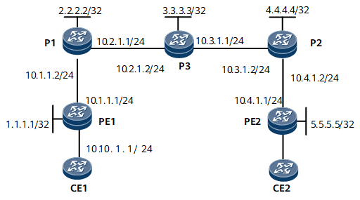
In Figure 1, CE1 and CE2 belong to the same L3VPN. They access the public network through PE1 and PE2 respectively. Various types of services are transmitted between CE1 and CE2. Transmitting a large number of common services deteriorates the efficiency of transmitting important services. To prevent this problem, the CBTS function can be configured. A CBTS allows traffic of a specific service class to be transmitted along a specified tunnel.
In this example, tunnel 1 transmits important services, and tunnel 2 transmits other packets.
Configuration Precautions
When configuring a TE tunnel group in an L3VPN over LDP over TE scenario, note that the destination IP address of a tunnel must be equal to the LSR ID of the egress.
Configuration Roadmap
The configuration roadmap is as follows:
Configure the IP address of a loopback interface as the LSR ID on each LSR and configure an IGP to advertise routes.
Configure OSPF TE on each TE-aware area, create an MPLS TE tunnel, and specify the service class for packets that can be transmitted on the tunnel.
Enable MPLS LDP in each non-TE-aware area and configure a remote LDP peer at the edge of the TE-aware area.
Configure the forwarding adjacency.
Configure multi-field traffic classification on nodes that connected to the L3VPN and configure behavior aggregate classification on LDP over TE links.
Data Preparation
To complete the configuration, you need the following data:
OSPF process ID and OSPF area ID
Policy for triggering the LSP establishment
Name and IP address of each remote LDP peer of P1 and P2
Link bandwidth attributes of the tunnel
Tunnel interface number, IP address, destination IP address, tunnel ID, tunnel signaling protocol (In this example, the default protocol of RSVP-TE is used), tunnel bandwidth, TE metric value, and link cost on each P.
Multi-field classifier name and traffic policy name
Procedure
- Assign an IP address to each interface.
Assign an IP address to each interface, including the loopback interface according to Figure 1. For configuration details, see Configuration Files in this section.
- Enable OSPF to advertise the route of the segment connected to each interface and the host route destined for each LSR ID. For configuration details, see Configuration Files in this section.
- Configure an EBGP peer relationship between each pair of a PE and a CE and an MP-IBGP peer relationship between two PEs.
For configuration details, see Configuration Files in this section.
- Enable MPLS on each LSR. Enable LDP to establish an LDP session between PE1 and P1, and between P2 and PE2. Enable RSVP-TE to establish an RSVP neighbor relationship between P1 and P2, and between P1 and P3.
# Configure PE1.
[~PE1] mpls lsr-id 1.1.1.1
[*PE1] mpls
[*PE1-mpls] lsp-trigger all
[*PE1-mpls] quit
[*PE1] mpls ldp
[*PE1-mpls-ldp] quit
[*PE1] interface gigabitethernet 0/1/0
[*PE1-GigabitEthernet0/1/0] mpls
[*PE1-GigabitEthernet0/1/0] mpls ldp
[*PE1-GigabitEthernet0/1/0] commit
[~PE1-GigabitEthernet0/1/0] quit
# Configure P1.
[~P1] mpls lsr-id 2.2.2.2
[*P1] mpls
[*P1-mpls] mpls te
[*P1-mpls] lsp-trigger all
[*P1-mpls] mpls rsvp-te
[*P1-mpls] mpls te cspf
[*P1-mpls] quit
[*P1] mpls ldp
[*P1-mpls-ldp] quit
[*P1] interface gigabitethernet 0/1/0
[*P1-GigabitEthernet0/1/0] mpls
[*P1-GigabitEthernet0/1/0] mpls ldp
[*P1-GigabitEthernet0/1/0] quit
[*P1] interface gigabitethernet 0/1/8
[*P1-GigabitEthernet0/1/8] mpls
[*P1-GigabitEthernet0/1/8] mpls te
[*P1-GigabitEthernet0/1/8] mpls rsvp-te
[*P1-GigabitEthernet0/1/8] commit
[~P1-GigabitEthernet0/1/8] quit
# Configure P3.
[~P3] mpls lsr-id 3.3.3.3
[*P3] mpls
[*P3-mpls] mpls te
[*P3-mpls] mpls rsvp-te
[*P3-mpls] quit
[*P3] interface gigabitethernet 0/1/0
[*P3-GigabitEthernet0/1/0] mpls
[*P3-GigabitEthernet0/1/0] mpls te
[*P3-GigabitEthernet0/1/0] mpls rsvp-te
[*P3-GigabitEthernet0/1/0] quit
[*P3] interface gigabitethernet 0/1/8
[*P3-GigabitEthernet0/1/8] mpls
[*P3-GigabitEthernet0/1/8] mpls te
[*P3-GigabitEthernet0/1/8] mpls rsvp-te
[*P3-GigabitEthernet0/1/8] commit
[~P3-GigabitEthernet0/1/8] quit
# Configure P2.
[~P2] mpls lsr-id 4.4.4.4
[*P2] mpls
[*P2-mpls] mpls te
[*P2-mpls] lsp-trigger all
[*P2-mpls] mpls rsvp-te
[*P2-mpls] mpls te cspf
[*P2-mpls] quit
[*P2] mpls ldp
[*P2-mpls-ldp] quit
[*P2] interface gigabitethernet 0/1/0
[*P2-GigabitEthernet0/1/0] mpls
[*P2-GigabitEthernet0/1/0] mpls te
[*P2-GigabitEthernet0/1/0] mpls rsvp-te
[*P2-GigabitEthernet0/1/0] quit
[*P2] interface gigabitethernet 0/1/8
[*P2-GigabitEthernet0/1/8] mpls
[*P2-GigabitEthernet0/1/8] mpls ldp
[*P2-GigabitEthernet0/1/8] commit
[~P2-GigabitEthernet0/1/8] quit
# Configure PE2.
[~PE2] mpls lsr-id 5.5.5.5
[*PE2] mpls
[*PE2-mpls] lsp-trigger all
[*PE2-mpls] quit
[*PE2] mpls ldp
[*PE2-mpls-ldp] quit
[*PE2] interface gigabitethernet 0/1/0
[*PE2-GigabitEthernet0/1/0] mpls
[*PE2-GigabitEthernet0/1/0] mpls ldp
[*PE2-GigabitEthernet0/1/0] commit
[~PE2-GigabitEthernet0/1/0] quit
After completing the preceding configurations, the local LDP sessions have been successfully established between PE1 and P1 and between P2 and PE2.
# Run the display mpls ldp session command on PE1, P1, P2, or PE2 to view information about the established LDP session.
[~PE1] display mpls ldp session
 LDP Session(s) in Public Network
 Codes: LAM(Label Advertisement Mode), SsnAge Unit(DDDD:HH:MM)
 A '*' before a session means the session is being deleted.
--------------------------------------------------------------------------
 PeerID             Status      LAM  SsnRole  SsnAge       KASent/Rcv
--------------------------------------------------------------------------
 2.2.2.2:0          Operational DU   Passive  0000:00:05   23/23
--------------------------------------------------------------------------
TOTAL: 1 Session(s) Found.
# Run the display mpls ldp peer command on PE1 to view information about the established LDP peer.
[~PE1] display mpls ldp peer
 LDP Peer Information in Public network
 A '*' before a peer means the peer is being deleted.
 -------------------------------------------------------------------------
 PeerID                 TransportAddress   DiscoverySource
 -------------------------------------------------------------------------
 2.2.2.2:0              2.2.2.2            GigabitEthernet0/1/0
 -------------------------------------------------------------------------
TOTAL: 1 Peer(s) Found.
# Run the display mpls lsp command on PE1 to view information about LDP LSP information. The command output shows that an RSVP-TE tunnel is not established. The following example uses the command output on PE1.
[~PE1] display mpls lsp
----------------------------------------------------------------------
                 LSP Information: LDP LSP
----------------------------------------------------------------------
FEC                In/Out Label  In/Out IF                      Vrf Name
1.1.1.1/32         3/NULL        GE0/1/0/-
2.2.2.2/32         NULL/3        -/GE0/1/0
2.2.2.2/32         1024/3        -/GE0/1/0
10.1.1.0/24        3/NUL         GE0/1/0/-
10.2.1.0/24        NULL/3        -/GE0/1/0
10.2.1.0/24        1025/3        -/GE0/1/0
- Configure a remote LDP session between P1 and P2.
# Configure P1.
[~P1] mpls ldp remote-peer lsrd
[*P1-mpls-ldp-remote-lsrd] remote-ip 4.4.4.4
[*P1-mpls-ldp-remote-lsrd] commit
[~P1-mpls-ldp-remote-lsrd] quit
# Configure P2.
[~P2] mpls ldp remote-peer lsrb
[*P2-mpls-ldp-remote-lsrb] remote-ip 2.2.2.2
[*P2-mpls-ldp-remote-lsrb] commit
[~P2-mpls-ldp-remote-lsrb] quit
After completing the preceding configurations, a remote LDP session is set up between P1 and P2. Run the display mpls ldp remote-peer command on P1 or P2 to view information about the remote session entity. The following example uses the command output on P1.
[~P1] display mpls ldp remote-peer lsrd LDP Remote Entity Information ------------------------------------------------------------------------------ Remote Peer Name: P2 Remote Peer IP : 4.4.4.4 LDP ID : 2.2.2.2:0 Transport Address : 2.2.2.2 Entity Status : Active Configured Keepalive Hold Timer : 45 Sec Configured Keepalive Send Timer : ---- Configured Hello Hold Timer : 45 Sec Negotiated Hello Hold Timer : 45 Sec Configured Hello Send Timer : ---- Configured Delay Timer : ---- Hello Packet sent/received : 425/382 ------------------------------------------------------------------------------ TOTAL: 1 Remote-Peer(s) Found. - Configure bandwidth attributes on each outbound interface along the link of the TE tunnel.
# Configure P1.
[~P1] interface gigabitethernet 0/1/8
[~P1-GigabitEthernet0/1/8] mpls te bandwidth max-reservable-bandwidth 20000
[*P1-GigabitEthernet0/1/8] mpls te bandwidth bc0 20000
[*P1-GigabitEthernet0/1/8] commit
[~P1-GigabitEthernet0/1/8] quit
# Configure P3.
[~P3] interface gigabitethernet 0/1/0
[~P3-GigabitEthernet0/1/0] mpls te bandwidth max-reservable-bandwidth 20000
[*P3-GigabitEthernet0/1/0] mpls te bandwidth bc0 20000
[*P3-GigabitEthernet0/1/0] quit
[*P3] interface gigabitethernet 0/1/8
[*P3-GigabitEthernet0/1/8] mpls te bandwidth max-reservable-bandwidth 20000
[*P3-GigabitEthernet0/1/8] mpls te bandwidth bc0 20000
[*P3-GigabitEthernet0/1/8] commit
[~P3-GigabitEthernet0/1/8] quit
# Configure P2.
[~P2] interface gigabitethernet 0/1/0
[~P2-GigabitEthernet0/1/0] mpls te bandwidth max-reservable-bandwidth 20000
[*P2-GigabitEthernet0/1/0] mpls te bandwidth bc0 20000
[*P2-GigabitEthernet0/1/0] commit
[~P2-GigabitEthernet0/1/0] quit
- Configure L3VPN access on PE1 and PE2 and configure multi-field classification on the inbound interface of PE1.
# Configure PE1.
[~PE1] ip vpn-instance VPNA
[*PE1-vpn-instance-VPNA] ipv4-family
[*PE1-vpn-instance-VPNA-af-ipv4] route-distinguisher 100:1
[*PE1-vpn-instance-VPNA-af-ipv4] vpn-target 111:1 both
[*PE1] interface gigabitethernet 0/1/8
[*PE1-GigabitEthernet0/1/8] ip binding vpn-instance VPNA
[*PE1] acl 2001
[*PE1-acl4-basic-2001] rule 10 permit source 10.40.0.0 0.255.255.255
[*PE1-acl4-basic-2001] quit
[*PE1] acl 2002
[*PE1-acl4-basic-2002] rule 20 permit source 10.50.0.0 0.255.255.255
[*PE1-acl4-basic-2002] quit
[*PE1] traffic classifier service1
[*PE1-classifier-service1] if-match acl 2001
[*PE1-classifier-service1] commit
[~PE1-classifier-service1] quit
[~PE1] traffic behavior behavior1
[*PE1-behavior-behavior1] service-class af1 color green
[*PE1-behavior-behavior1] commit
[~PE1-behavior-behavior1] quit
[~PE1] traffic classifier service2
[*PE1-classifier-service2] if-match acl 2002
[*PE1-classifier-service2] commit
[~PE1-classifier-service2] quit
[~PE1] traffic behavior behavior2
[*PE1-behavior-behavior2] service-class af2 color green
[*PE1-behavior-behavior2] commit
[~PE1-behavior-behavior2] quit
[~PE1] traffic policy test
[*PE1-trafficpolicy-test] classifier service1 behavior behavior1
[*PE1-trafficpolicy-test] classifier service2 behavior behavior2
[*PE1-trafficpolicy-test] commit
[~PE1-trafficpolicy-test] quit
[~PE1] interface gigabitethernet 0/1/8
[~PE1-GigabitEthernet0/1/8] traffic-policy test inbound
[~PE1-GigabitEthernet0/1/8] commit
[~PE1-GigabitEthernet0/1/8] quit
# Configure PE2.
[~PE2] ip vpn-instance VPNB
[*PE2-vpn-instance-VPNB] ipv4-family
[*PE2-vpn-instance-VPNB-af-ipv4] route-distinguisher 200:1
[*PE2-vpn-instance-VPNB-af-ipv4] vpn-target 111:1 both
[*PE2] interface gigabitethernet 0/1/8
[*PE2-GigabitEthernet0/1/8] ip binding vpn-instance VPNB
[*PE2-GigabitEthernet0/1/8] commit
[~PE2-GigabitEthernet0/1/8] quit
- Configure behavior aggregate classification on interfaces connecting PE1 to P1.
# Configure PE1.
[~PE1] interface gigabitethernet 0/1/0
[~PE1-GigabitEthernet0/1/0] trust upstream default
[*PE1-GigabitEthernet0/1/0] commit
[~PE1-GigabitEthernet0/1/0] quit
# Configure P1.
[~P1] interface gigabitethernet 0/1/0
[~P1-GigabitEthernet0/1/0] trust upstream default
[*PE1-GigabitEthernet0/1/0] commit
[~PE1-GigabitEthernet0/1/0] quit
- Configure a TE tunnel that originates from P1 and is destined for P2 and set the service class for each type of packets that can pass through the tunnel.

Run the mpls te service-class { service-class & <1-8> | default } command to configure the service class for packets transmitted along the tunnel.
# On P1, enable the IGP shortcut function on the tunnel interface and adjust the metric value to ensure that traffic destined for P2 or PE2 passes through the tunnel.
[~P1] interface tunnel1
[*P1-Tunnel1] ip address unnumbered interface LoopBack1
[*P1-Tunnel1] tunnel-protocol mpls te
[*P1-Tunnel1] destination 4.4.4.4
[*P1-Tunnel1] mpls te tunnel-id 100
[*P1-Tunnel1] mpls te bandwidth ct0 10000
[*P1-Tunnel1] mpls te igp shortcut
[*P1-Tunnel1] mpls te igp metric absolute 1
[*P1-Tunnel1] mpls te service-class af1 af2
[*P1-Tunnel1] quit
[*P1] interface tunnel12
[*P1-Tunnel2] ip address unnumbered interface LoopBack1
[*P1-Tunnel2] tunnel-protocol mpls te
[*P1-Tunnel2] destination 4.4.4.4
[*P1-Tunnel2] mpls te tunnel-id 200
[*P1-Tunnel2] mpls te bandwidth ct0 10000
[*P1-Tunnel2] mpls te igp shortcut
[*P1-Tunnel2] mpls te igp metric absolute 1
[*P1-Tunnel2] mpls te service-class default
[*P1-Tunnel2] quit
[*P1] ospf 1
[*P1-ospf-1] area 0
[*P1-ospf-1-area-0.0.0.0] network 2.2.2.2 0.0.0.0
[*P1-ospf-1-area-0.0.0.0] quit
[*P1-ospf-1] enable traffic-adjustment advertise
[*P1-ospf-1] commit
- Configure a tunnel that originates from P2 and is destined for P1.
# On P2, enable the IGP shortcut function on the tunnel interface and adjust the metric value to ensure that traffic destined for PE1 or P1 passes through the tunnel.
[~P2] interface tunnel1
[*P2-Tunnel1] ip address unnumbered interface LoopBack1
[*P2-Tunnel1] tunnel-protocol mpls te
[*P2-Tunnel1] destination 2.2.2.2
[*P2-Tunnel1] mpls te tunnel-id 101
[*P2-Tunnel1] mpls te bandwidth ct0 10000
[*P2-Tunnel1] mpls te igp shortcut
[*P2-Tunnel1] mpls te igp metric absolute 1
[*P2-Tunnel1] quit
[*P2] ospf 1
[*P2-ospf-1] area 0
[*P2-ospf-1-area-0.0.0.0] network 4.4.4.4 0.0.0.0
[*P2-ospf-1-area-0.0.0.0] quit
[*P2-ospf-1] enable traffic-adjustment advertise
[*P2-ospf-1] quit
[*P2] commit
Configuration Files
PE1 configuration file
#
sysname PE1
#
ip vpn-instance VPNA
 ipv4-family
  route-distinguisher 100:1
  apply-label per-instance
  vpn-target 111:1 export-extcommunity
  vpn-target 111:1 import-extcommunity
#
mpls lsr-id 1.1.1.1
#
mpls
 lsp-trigger all
#
mpls ldp
#
acl number 2001
 rule 10 permit source 10.40.0.0 0.255.255.255
#
acl number 2002
 rule 20 permit source 10.50.0.0 0.255.255.255
#
traffic classifier service1
 if-match acl 2001
#
traffic classifier service2
 if-match acl 2002
#
traffic behavior behavior1
 service-class af1 color green
#
traffic behavior behavior2
 service-class af2 color green
#
traffic policy test
 share-mode
 classifier service1 behavior behavior1
 classifier service2 behavior behavior2
#
interface GigabitEthernet0/1/0
 undo shutdown
 ip address 10.1.1.1 255.255.255.0
 mpls
 mpls ldp
 trust upstream default
#
interface GigabitEthernet0/1/8
 undo shutdown
 ip binding vpn-instance VPNA
 ip address 10.10.1.1 255.255.255.0
 traffic-policy test inbound
#
interface LoopBack1
 ip address 1.1.1.1 255.255.255.255
#
bgp 100
 peer 5.5.5.5 as-number 100
 peer 5.5.5.5 connect-interface LoopBack1
 #
 ipv4-family unicast
  undo synchronization
  peer 5.5.5.5 enable
 #
 ipv4-family vpnv4
  policy vpn-target
  peer 5.5.5.5 enable
 #
 ipv4-family vpn-instance VPNA
  peer 10.10.1.2 as-number 65410
#
ospf 1
 area 0.0.0.0
  network 1.1.1.1 0.0.0.0
  network 10.1.1.0 0.0.0.255
#
return
P1 configuration file
#
sysname P1
#
mpls lsr-id 2.2.2.2
#
mpls
 mpls te
 mpls rsvp-te
 mpls te cspf
 lsp-trigger all
#
mpls ldp
 #
 ipv4-family
#
mpls ldp remote-peer lsrd
 remote-ip 4.4.4.4
#
interface GigabitEthernet0/1/0
 undo shutdown
 ip address 10.1.1.2 255.255.255.0
 mpls
 mpls ldp
 trust upstream default
#
interface GigabitEthernet0/1/8
 undo shutdown
 ip address 10.2.1.1 255.255.255.0
 mpls
 mpls te
 mpls te bandwidth max-reservable-bandwidth 20000
 mpls te bandwidth bc0 20000
 mpls rsvp-te
#
interface LoopBack1
 ip address 2.2.2.2 255.255.255.255
#
interface Tunnel1
 ip address unnumbered interface LoopBack1
 tunnel-protocol mpls te
 destination 4.4.4.4
 mpls te tunnel-id 100
 mpls te bandwidth ct0 10000
 mpls te igp shortcut
 mpls te igp metric absolute 1
 mpls te service-class af1 af2
#
interface Tunnel2
 ip address unnumbered interface LoopBack1
 tunnel-protocol mpls te
 destination 4.4.4.4
 mpls te tunnel-id 200
 mpls te bandwidth ct0 10000
 mpls te igp shortcut
 mpls te igp metric absolute 1
 mpls te service-class default
#
ospf 1
 opaque-capability enable
 enable traffic-adjustment advertise
 area 0.0.0.0
  network 2.2.2.2 0.0.0.0
  network 10.1.1.0 0.0.0.255
  network 10.2.1.0 0.0.0.255
  mpls-te enable
#
return
P3 configuration file
#
sysname P3
#
mpls lsr-id 3.3.3.3
#
mpls
 mpls te
 mpls rsvp-te
#
interface GigabitEthernet0/1/0
 undo shutdown
 ip address 10.2.1.2 255.255.255.0
 mpls
 mpls te
 mpls te bandwidth max-reservable-bandwidth 20000
 mpls te bandwidth bc0 20000
 mpls rsvp-te
#
interface GigabitEthernet0/1/8
 undo shutdown
 ip address 10.3.1.1 255.255.255.0
 mpls
 mpls te
 mpls te bandwidth max-reservable-bandwidth 20000
 mpls te bandwidth bc0 20000
 mpls rsvp-te
#
interface LoopBack1
 ip address 3.3.3.3 255.255.255.255
#
ospf 1
 opaque-capability enable
 area 0.0.0.0
  network 3.3.3.3 0.0.0.0
  network 10.2.1.0 0.0.0.255
  network 10.3.1.0 0.0.0.255
  mpls-te enable
#
return
P2 configuration file
#
sysname P2
#
mpls lsr-id 4.4.4.4
#
mpls
 mpls te
 mpls rsvp-te
 mpls te cspf
 lsp-trigger all
#
mpls ldp
 #
 ipv4-family
#
mpls ldp remote-peer lsrb
 remote-ip 2.2.2.2
#
interface GigabitEthernet0/1/0
 undo shutdown
 ip address 10.3.1.2 255.255.255.0
 mpls
 mpls te
 mpls te bandwidth max-reservable-bandwidth 20000
 mpls te bandwidth bc0 20000
 mpls rsvp-te
#
interface GigabitEthernet0/1/8
 undo shutdown
 ip address 10.4.1.2 255.255.255.0
 mpls
 mpls ldp
#
interface LoopBack1
 ip address 4.4.4.4 255.255.255.255
#
interface Tunnel1
 ip address unnumbered interface LoopBack1
 tunnel-protocol mpls te
 destination 2.2.2.2
 mpls te tunnel-id 101
 mpls te bandwidth ct0 10000
 mpls te igp shortcut
 mpls te igp metric absolute 1
#
ospf 1
 opaque-capability enable
 enable traffic-adjustment advertise
 area 0.0.0.0
  network 4.4.4.4 0.0.0.0
  network 10.3.1.0 0.0.0.255
  network 10.4.1.0 0.0.0.255
  mpls-te enable
#
return
PE2 configuration file
#
sysname PE2
#
ip vpn-instance VPNB
 ipv4-family
  route-distinguisher 200:1
  apply-label per-instance
  vpn-target 111:1 export-extcommunity
  vpn-target 111:1 import-extcommunity
#
mpls lsr-id 5.5.5.5
#
mpls
 lsp-trigger all
#
mpls ldp
#
interface GigabitEthernet0/1/0
 undo shutdown
 ip address 10.4.1.1 255.255.255.0
 mpls
 mpls ldp
#
interface GigabitEthernet0/1/8
 undo shutdown
 ip binding vpn-instance VPNB
 ip address 10.11.1.1 255.255.255.0
#
interface LoopBack1
 ip address 5.5.5.5 255.255.255.255
#
bgp 100
 peer 1.1.1.1 as-number 100
 peer 1.1.1.1 connect-interface LoopBack1
 #
 ipv4-family unicast
  undo synchronization
  peer 1.1.1.1 enable
 #
 ipv4-family vpnv4
  policy vpn-target
  peer 1.1.1.1 enable
 #
 ipv4-family vpn-instance VPNB
  peer 10.11.1.2 as-number 65420
#
ospf 1
 area 0.0.0.0
  network 5.5.5.5 0.0.0.0
  network 10.4.1.0 0.0.0.255
#
return