Example for Configuring Tunneling of Special Link-Layer-Protocol Packets over a VPLS PW
CE1 and CE2 are non-Huawei devices. Both CEs support the Cisco Discovery Protocol (CDP). To ensure that these CEs can work with NetEngine 8000 Fs, you must establish a VPLS PW between PE1 and PE2. In this manner, CE1 and CE2 can transparently transmit CDP packets between each other over the PW and use CDP to discover each other.
Networking Requirements
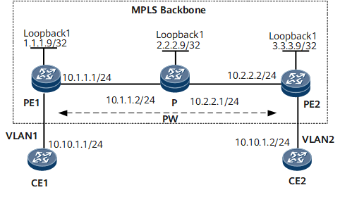
As shown in Figure 1, VPLS is enabled on PE1 and PE2. CE1 and CE2 are non-Huawei devices and connected to PE1 and PE2, respectively. The CEs belong to the same VPLS network. PWs are established with the Label Distribution Protocol (LDP) as the VPLS signaling protocol, and VPLS is configured for the CEs to communicate.
Both CEs support CDP. To ensure that these CEs can work with NetEngine 8000 Fs, you must use LDP as the signaling protocol to establish a VPLS PW between PE1 and PE2. In this manner, CE1 and CE2 can transparently transmit CDP packets between each other over the PW and use CDP to discover each other.
Device Name |
Interface |
IP Address |
|---|---|---|
CE1 |
GE 0/1/0.1 |
10.10.1.1/24 |
PE1 |
GE 0/1/0.1 |
- |
PE1 |
GE 0/1/8 |
10.1.1.1/24 |
PE1 |
Loopback 1 |
1.1.1.9/32 |
P |
GE 0/1/0 |
10.2.2.1/24 |
P |
GE 0/1/8 |
10.1.1.2/24 |
P |
Loopback 1 |
2.2.2.9/24 |
PE2 |
GE 0/1/0 |
- |
PE2 |
GE 0/1/8 |
10.2.2.2/24 |
PE2 |
Loopback 1 |
3.3.3.9/32 |
CE2 |
GE 0/1/0.1 |
10.10.1.2/24 |
Configuration Roadmap
The configuration roadmap is as follows:
Configure a routing protocol on the backbone network to achieve connectivity between devices.
Establish remote LDP sessions between PEs.
Establish a tunnel between PEs to transmit service data.
Enable MPLS L2VPN on PEs.
Create a VSI, configure LDP as the signaling protocol, and bind the VSI to an AC interface on each PE.
Enable transparent transmission of CDP packets on the AC interface on each PE connecting the PE to a CE.
Data Preparation
To complete the configuration, you need the following data:
VSI name and VSI ID
IP addresses of peers and tunnel policies used for setting up peer relationships
Names of interfaces bound to the VSI
Procedure
- Configure an IGP. In this example, OSPF is used.
After the configuration is complete, run the display ip routing-table command on PEs and the P. You can view the routes that the devices have learned from each other.
As shown in Figure 1, assign an IP address to each interface on PEs and the P. When configuring OSPF, advertise the 32-bit IP addresses of loopback interfaces, which are used as LSR IDs, on PEs and the P.
For details, see the following configuration files.
- Configure basic MPLS functions and LDP.
For details, see the following configuration files.
After the configuration is complete, run the display mpls ldp session command on PEs and the P. The command output shows that Status of the peer relationship between PE1 and PE2 and between PE2 and the P is Operational, which indicates that the peer relationships have been established. Run the display mpls lsp command to check whether the LSP is established.
- Set up remote LDP sessions between PEs.
# Configure PE1.
[*PE1] mpls ldp remote-peer 3.3.3.9
[*PE1-mpls-ldp-remote-3.3.3.9] remote-ip 3.3.3.9
[*PE1-mpls-ldp-remote-3.3.3.9] quit
[*PE1] commit
# Configure PE2.
[*PE2] mpls ldp remote-peer 1.1.1.9
[*PE2-mpls-ldp-remote-1.1.1.9] remote-ip 1.1.1.9
[*PE2-mpls-ldp-remote-1.1.1.9] quit
[*PE2] commit
After the configuration is complete, run the display mpls ldp session command on PE1 or PE2. The command output shows that Status of the peer relationship between PE1 and PE2 is Operational, which indicates that the peer relationship has been established.
- Enable MPLS L2VPN on PEs.
# Configure PE1.
[*PE1] mpls l2vpn
[*PE1-l2vpn] quit
[*PE1] commit
# Configure PE2.
[*PE2] mpls l2vpn
[*PE2-l2vpn] quit
[*PE2] commit
- Configure a VSI on PEs.
# Configure PE1.
[*PE1] vsi a2 static
[*PE1-vsi-a2] pwsignal ldp
[*PE1-vsi-a2-ldp] vsi-id 2
[*PE1-vsi-a2-ldp] peer 3.3.3.9
[*PE1-vsi-a2-ldp] commit
# Configure PE2.
[*PE2] vsi a2 static
[*PE2-vsi-a2] pwsignal ldp
[*PE2-vsi-a2-ldp] vsi-id 2
[*PE2-vsi-a2-ldp] peer 1.1.1.9
[*PE2-vsi-a2-ldp] commit
- Bind the VSI to the interfaces of the PEs.
# Configure PE1.
[*PE1] interface gigabitethernet0/1/0.1
[*PE1-GigabitEthernet0/1/0.1] shutdown
[*PE1-GigabitEthernet0/1/0.1] vlan-type dot1q 10
[*PE1-GigabitEthernet0/1/0.1] l2 binding vsi a2
[*PE1-GigabitEthernet0/1/0.1] undo shutdown
[*PE1-GigabitEthernet0/1/0.1] quit
[*PE1] commit
# Configure PE2.
[*PE2] interface gigabitethernet0/1/8.1
[*PE2-GigabitEthernet0/1/8.1] shutdown
[*PE2-GigabitEthernet0/1/8.1] vlan-type dot1q 10
[*PE2-GigabitEthernet0/1/8.1] l2 binding vsi a2
[*PE2-GigabitEthernet0/1/8.1] undo shutdown
[*PE2-GigabitEthernet0/1/8.1] quit
[*PE2] commit
- Enable transparent transmission of CDP packets on the PEs.
# Configure PE1.
[*PE1] interface gigabitethernet 0/1/0.1
[*PE1-GigabitEthernet0/1/0.1] link-protocol transport cdp
[*PE1-GigabitEthernet0/1/0.1] quit
[*PE1] commit
# Configure PE2.
[*PE2] interface gigabitethernet0/1/8.1
[*PE2-GigabitEthernet0/1/8.1] link-protocol transport cdp
[*PE2-GigabitEthernet0/1/8.1] quit
[*PE2] commit
- Configure CEs.
Configure IP addresses for GE 0/1/0.1 on CE1 and CE2. As the CEs are non-Huawei devices, their configurations are not provided here.
- Verify the configuration.
After the configurations are complete, run the display vsi name a2 verbose command on PE1. The command output shows that the VSI named a2 has established a PW to PE2, and the status of the VSI is Up.
<PE1> display vsi name a2 verbose
 ***VSI Name               : a2
    Administrator VSI      : no
    Isolate Spoken         : disable
    VSI Index              : 0
    PW Signaling           : ldp
    Member Discovery Style : static
    Bridge-domain Mode     : disable
    PW MAC Learn Style     : unqualify
    Encapsulation Type     : vlan
    MTU                    : 1500
    Diffserv Mode          : uniform
    Service Class          : --
    Color                  : --
    DomainId               : 255
    Domain Name            :
    Ignore AcState         : disable
    P2P VSI                : disable
    Create Time            : 0 days, 3 hours, 30 minutes, 31 seconds
    VSI State              : up
    VSI ID                 : 2
   *Peer Router ID         : 3.3.3.9
    primary or secondary   : primary
    ignore-standby-state   : no
    VC Label               : 23552
    Peer Type              : dynamic
    Session                : up
    Tunnel ID              : 0x2002001
    Broadcast Tunnel ID    : --
    Broad BackupTunnel ID  : --
    CKey                   : 2
    NKey                   : 3439331285
    Stp Enable             : 0
    PwIndex                : 2
    Interface Name         : GigabitEthernet0/1/0.1
    State                  : up
    Last Up Time           : 2012-08-15 15:41:59
    Total Up Time          : 0 days, 0 hours, 1 minutes, 2 seconds
   **PW Information:
   *Peer Ip Address        : 3.3.3.9
    PW State               : up
    Local VC Label         : 23552
    Remote VC Label        : 23552
    PW Type                : label
    Tunnel ID              : 0x0000000001006ad122
    Broadcast Tunnel ID    : --
    Broad BackupTunnel ID  : --
    Ckey                   : 36033
    Nkey                   : 3053453715
    Main PW Token          : 0x0
    Slave PW Token         : 0x0
    Tnl Type               : ldp
    OutInterface           : LDP LSP
    Backup OutInterface    : --
    Stp Enable             : 0
    PW Last Up Time        : 2012-08-15 15:41:59
    PW Total Up Time       : 0 days, 0 hours, 1 minutes, 3 seconds
CE1 (10.1.1.1) can ping CE2 (10.1.1.2) successfully.
<CE1> ping 10.1.1.2
  PING 10.1.1.2: 56  data bytes, press CTRL_C to break
    Reply from 10.1.1.2: bytes=56 Sequence=1 ttl=255 time=90 ms
    Reply from 10.1.1.2: bytes=56 Sequence=2 ttl=255 time=77 ms
    Reply from 10.1.1.2: bytes=56 Sequence=3 ttl=255 time=34 ms
    Reply from 10.1.1.2: bytes=56 Sequence=4 ttl=255 time=46 ms
    Reply from 10.1.1.2: bytes=56 Sequence=5 ttl=255 time=94 ms
  --- 10.1.1.2 ping statistics ---
    5 packet(s) transmitted
    5 packet(s) received
    0.00% packet loss
    round-trip min/avg/max = 34/68/94 ms
CE1 and CE2 can discover each other using the CDP.
Configuration Files
Configuration file of PE1
#
 sysname PE1
#
 mpls lsr-id 1.1.1.9
 mpls
#
 mpls l2vpn
#
vsi a2 static
 pwsignal ldp
  vsi-id 2
  peer 3.3.3.9
#
mpls ldp
#
 mpls ldp remote-peer 3.3.3.9
 remote-ip 3.3.3.9
#
interface GigabitEthernet0/1/0.1
 vlan-type dot1q 10
 link-protocol transport cdp
 l2 binding vsi a2
#
interface GigabitEthernet0/1/8
 ip address 10.1.1.1 255.255.255.0
 mpls
 mpls ldp
#
interface LoopBack1
 ip address 1.1.1.9 255.255.255.255
#
ospf 1
 area 0.0.0.0
  network 1.1.1.9 0.0.0.0
  network 10.1.1.0 0.0.0.255
#
return
Configuration file of the P
#
 sysname P
#
 mpls lsr-id 2.2.2.9
 mpls
#
mpls ldp
#
interface GigabitEthernet0/1/0
 ip address 10.1.1.2 255.255.255.0
 mpls
 mpls ldp
#
interface GigabitEthernet0/1/8
 ip address 10.2.2.1 255.255.255.0
 mpls
 mpls ldp
#
interface LoopBack1
 ip address 2.2.2.9 255.255.255.255
#
ospf 1
 area 0.0.0.0
  network 10.1.1.0 0.0.0.255
  network 10.2.2.0 0.0.0.255
  network 2.2.2.9 0.0.0.0
#
return
Configuration file of PE2
#
 sysname PE2
#
 mpls lsr-id 3.3.3.9
 mpls
#
 mpls l2vpn
#
vsi a2 static
 pwsignal ldp
  vsi-id 2
  peer 1.1.1.9
#
mpls ldp
#
 mpls ldp remote-peer 1.1.1.9
 remote-ip 1.1.1.9
#
interface GigabitEthernet0/1/0
 ip address 10.2.2.2 255.255.255.0
 mpls
 mpls ldp
#
interface GigabitEthernet0/1/8.1
 vlan-type dot1q 10
 link-protocol transport cdp
 l2 binding vsi a2
#
interface LoopBack1
 ip address 3.3.3.9 255.255.255.255
#
ospf 1
 area 0.0.0.0
  network 3.3.3.9 0.0.0.0
  network 10.2.2.0 0.0.0.255
#
return