Example for Configuring Tunneling of Special Link-Layer-Protocol Packets over a VPWS PW
CE1 and CE2 are non-Huawei devices. Both CEs support the Cisco Discovery Protocol (CDP). To ensure that these CEs can work with NetEngine 8000 Fs, you must establish a VPWS PW between PE1 and PE2. In this manner, CE1 and CE2 can transparently transmit CDP packets between each other over the PW and use CDP to discover each other.
Networking Requirements
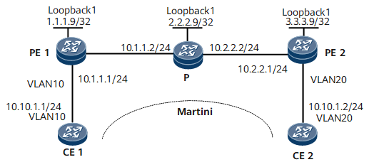
As shown in Figure 1, CE1 and CE2 are connected to PE1 and PE2 respectively through VLANs.
A Martini VPWS is set up between CE1 and CE2.
CE1 and CE2 are non-Huawei devices. Both CEs support the CDP. To ensure that these CEs can work with NetEngine 8000 Fs, you must establish a VPWS PW between PE1 and PE2. In this manner, CE1 and CE2 can transparently transmit CDP packets between each other over the PW and discover each other based on the CDP.
Device Name |
Interface |
IP Address |
|---|---|---|
CE1 |
GE 0/1/0.1 |
10.10.1.1/24 |
PE1 |
GE 0/1/0.1 |
- |
PE1 |
GE 0/1/8 |
10.1.1.1/24 |
PE1 |
Loopback 1 |
1.1.1.9/32 |
P |
GE 0/1/0 |
10.2.2.2/24 |
P |
GE 0/1/8 |
10.1.1.2/24 |
P |
Loopback 1 |
2.2.2.9/24 |
PE2 |
GE 0/1/0 |
- |
PE2 |
GE 0/1/8 |
10.2.2.1/24 |
PE2 |
Loopback 1 |
3.3.3.9/32 |
CE2 |
GE 0/1/0.1 |
10.10.1.2/24 |
Configuration Roadmap
The configuration roadmap is as follows:
Configure a routing protocol on PEs and the P on the backbone network to achieve connectivity between these devices and enable MPLS on them.
Establish an LSP between PEs to transmit data. The default tunnel policy is used in this example.
Enable MPLS L2VPN on PEs and create VCs.
Configure VLANIF interfaces so that CEs can access PEs through VLANs.
Enable transparent transmission of CDP packets on the AC interface on each PE connecting the PE to a CE.
Data Preparation
To complete the configuration, you need the following data:
VLAN sub-interface numbers
Name of the remote peer of each PE
VC IDs
Procedure
- Configure CEs.
# Configure CE1.
<HUAWEI> system-view
[~HUAWEI] sysname CE1
[*HUAWEI] commit
[*CE1] interface gigabitethernet 0/1/0
[*CE1-GigabitEthernet0/1/0] undo shutdown
[*CE1-GigabitEthernet0/1/0] quit
[*CE1] interface gigabitethernet 0/1/0.1
[*CE1-GigabitEthernet0/1/0.1] vlan-type dot1q 10
[*CE1-GigabitEthernet0/1/0.1] ip address 10.10.1.1 24
[*CE1-GigabitEthernet0/1/0.1] undo shutdown
[*CE1-GigabitEthernet0/1/0.1] quit
[*CE1] commit
# Configure CE2.
<HUAWEI> system-view
[~HUAWEI] sysname CE2
[*HUAWEI] commit
[*CE2] interface gigabitethernet 0/1/0
[*CE2-GigabitEthernet0/1/0] undo shutdown
[*CE2-GigabitEthernet0/1/0] quit
[*CE2] interface gigabitethernet 0/1/0.1
[*CE2-GigabitEthernet0/1/0.1] vlan-type dot1q 20
[*CE2-GigabitEthernet0/1/0.1] ip address 10.10.1.2 24
[*CE2-GigabitEthernet0/1/0.1] undo shutdown
[*CE2-GigabitEthernet0/1/0.1] quit
[*CE2] commit
- Configure an IGP on the MPLS backbone network. OSPF is used in this example.
As shown in Figure 1, assign an IP address to each interface on PEs and the P. When configuring OSPF, advertise the 32-bit IP addresses of loopback interfaces, which are used as LSR IDs, on PEs and the P.
The configuration details are not provided here.
After the configuration is complete, OSPF neighbor relationships can be set up between PE1, the P, and PE2. Run the display ospf peer command. The command output shows that the neighbor status is Full. Run the display ip routing-table command. The command output shows that PEs have learned the routes to Loopback1 from each other.
- Configure basic MPLS functions and LDP on the MPLS backbone network.
# Configure PE1.
[*PE1] mpls lsr-id 1.1.1.9
[*PE1] mpls
[*PE1-mpls] quit
[*PE1] mpls ldp
[*PE1-mpls-ldp] quit
[*PE1] interface gigabitethernet 0/1/8
[*PE1-GigabitEthernet0/1/8] mpls
[*PE1-GigabitEthernet0/1/8] mpls ldp
[*PE1-GigabitEthernet0/1/8] quit
[*PE1] commit
# Configure the P.
[*P] mpls lsr-id 2.2.2.9
[*P] mpls
[*P-mpls] quit
[*P] mpls ldp
[*P-mpls-ldp] quit
[*P] interface gigabitethernet 0/1/0
[*P-GigabitEthernet0/1/0] mpls
[*P-GigabitEthernet0/1/0] mpls ldp
[*P-GigabitEthernet0/1/0] quit
[*P] interface gigabitethernet 0/1/8
[*P-GigabitEthernet0/1/8] mpls
[*P-GigabitEthernet0/1/8] mpls ldp
[*P-GigabitEthernet0/1/8] quit
[*P] commit
# Configure PE2.
[*PE2] mpls lsr-id 3.3.3.9
[*PE2] mpls
[*PE2-mpls] quit
[*PE2] mpls ldp
[*PE2-mpls-ldp] quit
[*PE2] interface gigabitethernet 0/1/8
[*PE2-GigabitEthernet0/1/8] mpls
[*PE2-GigabitEthernet0/1/8] mpls ldp
[*PE2-GigabitEthernet0/1/8] quit
[*PE2] commit
- Set up remote LDP sessions between PEs.
# Configure PE1.
[*PE1] mpls ldp remote-peer 3.3.3.9
[*PE1-mpls-ldp-remote-3.3.3.9] remote-ip 3.3.3.9
[*PE1-mpls-ldp-remote-3.3.3.9] quit
[*PE1] commit
# Configure PE2.
[*PE2] mpls ldp remote-peer 1.1.1.9
[*PE2-mpls-ldp-remote-1.1.1.9] remote-ip 1.1.1.9
[*PE2-mpls-ldp-remote-1.1.1.9] quit
[*PE2] commit
After the configuration is complete, run the display mpls ldp session command on PE1 to view information about LDP sessions. The command output shows that both remote LDP sessions have been established.
The command output on PE1 is used as an example.
<PE1> display mpls ldp session LDP Session(s) in Public Network ------------------------------------------------------------------------------ Peer-ID Status LAM SsnRole SsnAge KA-Sent/Rcv ------------------------------------------------------------------------------ 2.2.2.9:0 Operational DU Passive 0000:00:09 40/40 3.3.3.9:0 Operational DU Passive 0000:00:09 37/37 ------------------------------------------------------------------------------ TOTAL: 2 session(s) Found. LAM : Label Advertisement Mode SsnAge Unit : DDDD:HH:MM - Enable MPLS L2VPN on PEs and create VCs.
# Configure PE1: Create a VC on GE 0/1/0.1 that is connected to CE1.
[*PE1] mpls l2vpn
[*PE1-l2vpn] mpls l2vpn default martini
[*PE1-l2vpn] quit
[*PE1] interface gigabitethernet 0/1/0
[*PE1-GigabitEthernet0/1/0] undo shutdown
[*PE1-GigabitEthernet0/1/0] quit
[*PE1] interface gigabitethernet 0/1/0.1
[*PE1-GigabitEthernet0/1/0.1] vlan-type dot1q 10
[*PE1-GigabitEthernet0/1/0.1] mpls l2vc 3.3.3.9 101
[*PE1-GigabitEthernet0/1/0.1] quit
[*PE1] commit
# Configure PE2: Create a VC on GE 0/1/0.1 that is connected to CE2.
[*PE2] mpls l2vpn
[*PE2-l2vpn] mpls l2vpn default martini
[*PE2-l2vpn] quit
[*PE2] interface gigabitethernet 0/1/0
[*PE2-GigabitEthernet0/1/0] undo shutdown
[*PE2-GigabitEthernet0/1/0] quit
[*PE2] interface gigabitethernet 0/1/0.1
[*PE2-GigabitEthernet0/1/0.1] vlan-type dot1q 20
[*PE2-GigabitEthernet0/1/0.1] mpls l2vc 1.1.1.9 101
[*PE2-GigabitEthernet0/1/0.1] quit
[*PE2] commit
- Enable transparent transmission of CDP packets on the PEs.
# Configure PE1.
[*PE1] interface gigabitethernet 0/1/0.1
[*PE1-GigabitEthernet0/1/0.1] link-protocol transport cdp
[*PE1-GigabitEthernet0/1/0.1] quit
[*PE1] commit
# Configure PE2.
[*PE2] interface gigabitethernet 0/1/0.1
[*PE2-GigabitEthernet0/1/0.1] link-protocol transport cdp
[*PE2-GigabitEthernet0/1/0.1] quit
[*PE2] commit
- Verify the configuration.
Check L2VPN connections on PEs. You can view that an L2VC connection has been set up and is Up.
The command output on PE1 is used as an example.
<PE1> display mpls l2vc interface gigabitethernet 0/1/0.1
 *client interface       : GigabitEthernet0/1/0.1 is up
  session state          : up
  AC state               : up
  VC state               : up
  VC ID                  : 101
  VC type                : VLAN
  destination            : 3.3.3.9
  local group ID         : 0            remote group ID      : 0
  local VC label         : 21504        remote VC label      : 21504
  local AC OAM State     : up
  local PSN State        : up
  local forwarding state : forwarding
  remote AC OAM state    : up
  remote PSN state       : up
  remote forwarding state: forwarding
  BFD for PW             : disable
  manual fault           : not set
  active state           : active
  forwarding entry       : exist
  link state             : up
  local VC MTU           : 1500         remote VC MTU        : 1500
  local VCCV             : Disable
  remote VCCV            : Disable
  local control word     : disable      remote control word  : disable
  tunnel policy name     : --
  traffic behavior name  : --
  PW template name       : --
  primary or secondary   : primary
  VC tunnel/token info   : 1 tunnels/tokens
    NO.0  TNL type : lsp   , TNL ID : 0x2002003
  create time            : 0 days, 0 hours, 4 minutes, 19 seconds
  up time                : 0 days, 0 hours, 2 minutes, 40 seconds
  last change time       : 0 days, 0 hours, 2 minutes, 40 seconds
  VC last up time : 2008-07-24 12:31:31
  VC total up time: 0 days, 2 hours, 12 minutes, 51 seconds
CE1 and CE2 can ping each other successfully.
The command output on CE1 is used as an example.
<CE1> ping 10.10.1.2
  PING 10.10.1.2: 56  data bytes, press CTRL_C to break
    Reply from 10.10.1.2: bytes=56 Sequence=1 ttl=255 time=31 ms
    Reply from 10.10.1.2: bytes=56 Sequence=2 ttl=255 time=10 ms
    Reply from 10.10.1.2: bytes=56 Sequence=3 ttl=255 time=5 ms
    Reply from 10.10.1.2: bytes=56 Sequence=4 ttl=255 time=2 ms
    Reply from 10.10.1.2: bytes=56 Sequence=5 ttl=255 time=28 ms
  --- 10.10.1.2 ping statistics ---
    5 packet(s) transmitted
    5 packet(s) received
    0.00% packet loss
    round-trip min/avg/max = 2/15/31 ms
Configuration Files
Configuration file of CE1
#
 sysname CE1
#
interface GigabitEthernet0/1/0
#
interface GigabitEthernet0/1/0.1
 vlan-type dot1q 10
 ip address 10.10.1.1 255.255.255.0
#
return
Configuration file of PE1
#
 sysname PE1
#
 mpls lsr-id 1.1.1.9
 mpls
#
 mpls l2vpn
  mpls l2vpn default martini
#
mpls ldp
#
 mpls ldp remote-peer 3.3.3.9
 remote-ip 3.3.3.9
#
interface GigabitEthernet0/1/0
#
interface GigabitEthernet0/1/0.1
 vlan-type dot1q 10
 link-protocol transport cdp
 mpls l2vc 3.3.3.9 101
#
interface GigabitEthernet0/1/8
 ip address 10.1.1.1 255.255.255.0
 mpls
 mpls ldp
#
interface LoopBack1
 ip address 1.1.1.9 255.255.255.255
#
ospf 1
 area 0.0.0.0
  network 1.1.1.9 0.0.0.0
  network 10.1.1.0 0.0.0.255
#
return
Configuration file of the P
#
 sysname P
#
 mpls lsr-id 2.2.2.9
 mpls
#
mpls ldp
#
interface GigabitEthernet0/1/0
 ip address 10.2.2.2 255.255.255.0
 mpls
 mpls ldp
#
interface GigabitEthernet0/1/8
 ip address 10.1.1.2 255.255.255.0
 mpls
 mpls ldp
#
interface LoopBack1
 ip address 2.2.2.9 255.255.255.255
#
ospf 1
 area 0.0.0.0
  network 2.2.2.9 0.0.0.0
  network 10.1.1.0 0.0.0.255
  network 10.2.2.0 0.0.0.255
#
return
Configuration file of PE2
#
 sysname PE2
#
 mpls lsr-id 3.3.3.9
 mpls
#
 mpls l2vpn
  mpls l2vpn default martini
#
mpls ldp
#
 mpls ldp remote-peer 1.1.1.9
 remote-ip 1.1.1.9
#
interface GigabitEthernet0/1/0
#
interface GigabitEthernet0/1/0.1
 vlan-type dot1q 20
 link-protocol transport cdp
 mpls l2vc 1.1.1.9 101
#
interface GigabitEthernet0/1/8
 ip address 10.2.2.1 255.255.255.0
 mpls
 mpls ldp
#
interface LoopBack1
 ip address 3.3.3.9 255.255.255.255
#
ospf 1
 area 0.0.0.0
  network 3.3.3.9 0.0.0.0
  network 10.2.2.0 0.0.0.255
#
return
Configuration file of CE2
#
 sysname CE2
#
interface GigabitEthernet0/1/0
#
interface GigabitEthernet0/1/0.1
 vlan-type dot1q 20
 ip address 10.10.1.2 255.255.255.0
#
return