Application Scenario for IPoEv4 Access
IPoE users include individual users and leased-line users.
Typical Applications of IPoE - Individual users
An individual user has independent service attributes, and a BRAS performs separate authentication and charging for an individual user. Individual users can be categorized into Layer 2 access users and Layer 3 access users.
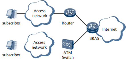
A Layer 2 access user accesses a BRAS through an Ethernet device (such as a LAN switch) or an ADSL device (such as a DSLAM). An access user can be allocated with a DHCP address on a local BRAS or on a remote DHCP server.
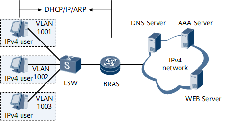
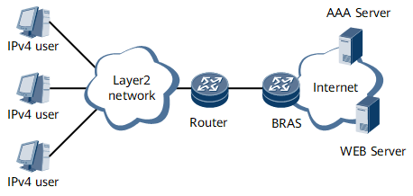
- A Layer 2 access user with address allocation on a local BRAS:
Figure 1 shows address allocation on a local BRAS.
A Layer 2 user can go online by sending a DHCP, IP, or ARP packet.
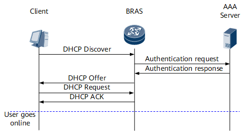
- By Sending a DHCP Packet:
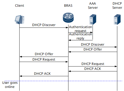
Figure 2 shows how a Layer 2 user goes online by sending a DHCP packet.
A DHCP client sends a DHCP Discover or DHCP Request packet to a BRAS.
After receiving the DHCP Discover or DHCP Request packet, the BRAS performs authentication, authorization, address allocation, forwarding control, and accounting management. In addition, the BRAS sends the IP address and parameters to the DHCP client by forwarding a DHCP Offer or DHCP ACK packet.
Only the user who successfully logs in to the BRAS can access the Internet. The user cannot access the Internet through the BRAS by using an address that is not allocated by the BRAS. IP addresses are locally managed. Therefore, the allocation, release, and lease extension of IP addresses must be performed on the BRAS.
By Sending an IP/ARP Packet:
Both a static user and a user logged out abnormally can go online by sending IP or ARP packets.
A static user has been assigned a fixed IP address on the client and does not need to be assigned an address on the BRAS. Therefore, the static user can go online only by sending IP or ARP packets. After receiving an IP or ARP packet from a user, the BRAS resolves parameters such as the IP address and the MAC address and determines whether the user is legal. Then, the BRAS performs binding authentication for the user. After passing the authentication, the user can log in and access the network.
A user logged out abnormally is the user that logs out because ARP probing fails, the idle connection is cut off, or a management command is executed to cut off the client. In this case, the user can enable the client to access the network by sending IP or ARP packets.
- By Sending a DHCP Packet:
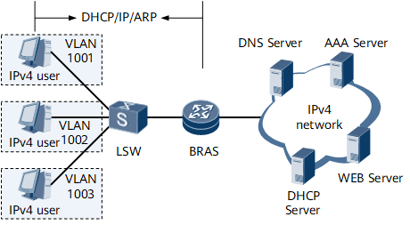
- A Layer 2 access user with address allocation on a remote DHCP server:
A DHCP access user can obtain an IP address from a remote DHCP server. In this case, the BRAS performs only user authentication, authorization, accounting, and forwarding control but does not manage IP addresses. The BRAS forwards the DHCP packet from a user to the remote DHCP server and sends the reply from the DHCP server to the DHCP client. Figure 3 shows the address allocation process through a remote DHCP server.
Figure 4 shows the process of remote login of a DHCP user.
By applying a remote address pool in a domain, the BRAS can enable the remote DHCP server to allocate an address of an access user. A remote address pool does not contain any IP addresses but indicates the corresponding DHCP server. When a remote address pool is used, the BRAS replaces the user to send a DHCP Request packet to apply for an IP address from the DHCP server or extend the address lease, or relays the DHCP Request packet from the user.
A remote address pool can be bound to a DHCP server group. You can configure a maximum of two DHCP servers in each DHCP server group. If two DHCP servers are configured, they can work either in master/slave mode or in load balance mode. By default, the two DHCP servers work in master/slave mode.
- In master/slave mode, the master and slave DHCP servers are determined based on the sequence in which they are added to a DHCP server group. The DHCP server added earlier is the master and the DHCP server added later is the slave. During IP address assignment, the master server is used preferentially to assign IP addresses. If the addresses in the address pool bound to the master DHCP server are used up, the slave DHCP server is used.
- In load balancing mode, the two DHCP servers assign IP addresses based on weights. The weight of each DHCP server is configured when the server is added to a DHCP server group. For example, 100 users apply for IP addresses and server A and server B have weights being 60 and 40 respectively. Therefore, server A allocates 60 IP addresses and server B allocates 40 IP addresses.
- In polling mode: The BRAS sends request packets to all servers and selects the server that receives the packets first. Subsequent packets, except for the discover and select request packets, are sent to only the selected server.
- A Layer 3 access user adopting Web authentication:
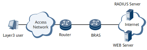
The BRAS does not know the MAC address of a user accessing the network through a Layer 3 device. Therefore, the BRAS does not allocate an IP address to a user who adopts Web authentication. A Layer 3 device, allocates an IP address to a user accessing the network through a Layer 3 device. After receiving an IP packet from a Layer 3 user, the BRAS checks whether it supports the Layer 3 user. If yes, the BRAS allows the user to perform Web authentication. After the client visits the web page and submits the user name and password, the Layer 3 user can access the network if it passes authentication.
Figure 5 shows the networking diagram of Layer 3 access users adopting Web authentication.
- A Layer 3 DHCP user:
In the situation that a user accesses the network through a Layer 3 device, a Layer 3 device acts as a DHCP relay agent and relays the DHCP packet from the client to the BRAS. After authenticating the user, the BRAS allocates an idle IP address to the user according to the giaddr field. Alternatively, the RADIUS server can allocate an IP address to the user and send the DHCP Response packet to the client.
Figure 6 shows the networking diagram of Layer 3 access users adopting Web authentication.
The address pool selection mode for Layer 3 access is different from that for Layer 2 access. For a Layer 2 access user, the address pool searched is in the domain to which the user belongs. For a Layer 3 access user, the address pool of the same gateway IP address is searched according to the giaddr field in the DHCP packet. This ensures that the allocated address is on the same network segment with the gateway IP address.
Typical Applications of IPoE - Leased-line Users
Leased line access refers to the access mode in which a certain Ethernet interface on the BRAS or certain VLANs on a certain interface of the BRAS are leased by a group of users. Multiple users can access the network through one leased line, but the BRAS considers all the users as a single user. The BRAS uniformly performs authentication, accounting, bandwidth control, access right control, and QoS management for the users that access the network through one leased line. According to the networking modes of leased line access, leased lines can be classified into Layer 2 leased lines, and Layer 3 leased lines.
Layer 2 leased line
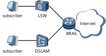
Layer 2 leased line access refers to the access mode in which a user accesses a certain interface on the BRAS or a certain VLAN on a certain interface of the BRAS through a LAN switch or a DSLAM. A Layer 2 leased line is connected to the network when the protocol status on the interface is Up. A leased line user can access the network through DHCP or ARP. A leased line user allocated with a dynamic IP address accesses the network through DHCP; a leased line user allocated with a static IP address accesses the network through ARP. The services of leased line users are controlled through the service control policy of the leased line regardless of the access modes of users. All the traffic passes through the leased line and the BRAS restricts the bandwidth of the leased line in a unified manner. Figure 7 shows Layer 2 leased line access.
Layer 3 leased line
Layer 3 leased line access refers to the access mode in which a user accesses a certain interface on the BRAS or a certain VLAN on a certain interface of the BRAS through a Layer 3 device. When this access mode is adopted, the BRAS performs the forwarding function. The access Layer 3 device is in charge of assigning IP addresses to Layer 3 leased line users. The BRAS is in charge of only packet forwarding and validity inspection. A Layer 3 leased line is connected to the network when the protocol status on the interface is Up. Then, the users of the leased line can access the network without accessing the BRAS. The services of the users of the Layer 3 leased line are controlled through the service control policy of the leased line. All the traffic passes through the leased line and the BRAS restricts the bandwidth of the leased line in a unified manner.
Figure 8 shows Layer 3 leased line access.
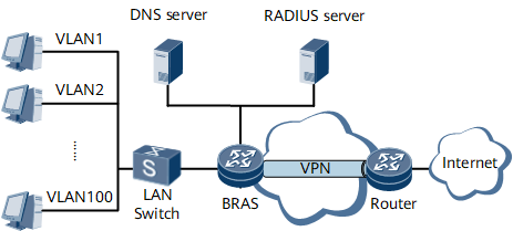
Layer 2 VPN leased line
The Layer 2 VPN leased line access mode is similar to the Layer 2 leased line access mode except that in this mode, each access interface is bound to a Layer 2 VPN. When the Layer 2 VPN leased line access mode is adopted, the BRAS functions as a UPE. A Layer 2 VPN leased line is connected to the network when the protocol status on the interface is Up. Then, the users of the leased line can access the network without accessing the BRAS. The services of leased line users are controlled through the service control policy of the leased line regardless of the access modes of users. All the traffic passes through the leased line and the BRAS restricts the bandwidth of the leased line in a unified manner.
Figure 9 shows Layer 2 VPN leased line access.
Typical Application of IPoE - BRAS Access Through L2VPN Termination
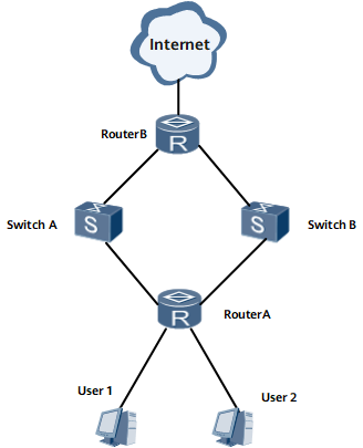
Router B uses OSPF to exchange traffic with Router A through interfaces on multiple boards in load-balancing mode. Traffic from the same user may be sent from different boards. Router B uses PBR to send traffic from the same user but different boards through the backplane to the same authentication board. In the preceding process, VE interfaces' internal loopback is required to support BRAS access through L2VPN termination, so that user authentication is complete after service traffic enters boards again.

Typical Application of IPoE - BRAS Access Through L3VPN Termination
Router B uses OSPF to exchange traffic with Router A through interfaces on multiple boards in load-balancing mode. Traffic from the same user may be sent from different boards. Router B uses PBR to send traffic from the same user but different boards through the backplane to the same authentication board. In the preceding process, VE interfaces' internal loopback on the NP is required to support BRAS access through L3VPN termination, so that Layer 3 static user authentication is complete after service traffic enters boards again.