CAR
What Is CAR
In traffic policing, committed access rate (CAR) is used to control traffic. CAR uses token buckets to measure traffic and determines whether a packet is conforming to the specification.
CAR has the following two functions:
Rate limit: Only packets allocated enough tokens are allowed to pass so that the traffic rate is restricted.
Traffic classification: Packets are marked internal priorities, such as the scheduling precedence and drop precedence, based on the measurement performed by token buckets.
CAR Process
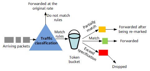
When a packet arrives, the device matches the packet against matching rules. If the packet matches a rule, the router uses token buckets to meter the traffic rate.
The router marks the packet red, yellow, or green based on the metering result. Red indicates that the traffic rate exceeds the specifications. Yellow indicates that the traffic rate exceeds the specifications but is within an allowed range. Green indicates that the traffic rate is conforming to the specifications.
The device drops packets marked red, re-marks and forwards packets marked yellow, and forwards packets marked green.
Marking Process of CAR
NetEngine 8000 Fs conform to relevant standards to implement CAR. CAR allows tokens to be added to a token bucket when a packet arrives. The number of tokens that are required is obtained using the following format: Number of required tokens = Committed information rate (CIR) x Period between the current time and the most recent time tokens are added. After tokens are put into a token bucket, the system determines whether the number of tokens is enough for the packet.
CAR supports srTCM with single bucket, srTCM with two buckets, and trTCM. This section provides examples of the three marking methods in Color-Blind mode. The implementation in Color-Aware mode is similar to that in Color-Blind mode.
SrTCM with Single Bucket
This example uses the CIR 1 Mbit/s, the committed burst size (CBS) 2000 bytes, and the excess burst size (EBS) 0. The EBS 0 indicates that only bucket C is used. Bucket C is initially full of tokens.
- If the first arriving packet is 1500 bytes long, the packet is marked green because the number of tokens in bucket C is greater than the packet length. The number of tokens in bucket C then decreases by 1500 bytes, with 500 bytes remaining.
- Assume that the second packet arriving at the interface after a delay of 1 ms is 1500 bytes long. Additional 125-byte tokens are put into bucket C (CIR x time period = 1 Mbit/s x 1 ms = 1000 bits = 125 bytes). Bucket C now has 625-byte tokens, which are not enough for the 1500-byte second packet. Therefore, the second packet is marked red.
- Assume that the third packet arriving at the interface after a delay of 1 ms is 1000 bytes long. Additional 125-byte tokens are put into bucket C (CIR x time period = 1 Mbit/s x 1 ms = 1000 bits = 125 bytes). Bucket C now has 750-byte tokens, which are not enough for the 1000-byte third packet. Therefore, the third packet is marked red.
- Assume that the fourth packet arriving at the interface after a delay of 20 ms is 1500 bytes long. Additional 2500-byte tokens are put into bucket C (CIR x time period = 1 Mbit/s x 20 ms = 20000 bits = 2500 bytes). This time 3250-byte tokens are destined for bucket C, but the excess 1250-byte tokens over the CBS (2000 bytes) are dropped. Therefore, bucket C has 2000-byte tokens, which are enough for the 1500-byte fourth packet. The fourth packet is marked green, and the number of tokens in bucket C decreases by 1500 bytes to 500 bytes.
The following table illustrates this process:
No.
Time
Packet Length
Delay
Token Addition
Tokens in Bucket C Before Packet Processing
Tokens in Bucket C After Packet Processing
Marking
-
-
-
-
-
2000
2000
-
1
0
1500
0
0
2000
500
Green
2
1
1500
1
125
625
625
Red
3
2
1000
1
125
750
750
Red
4
22
1500
20
2500
2000
500
Green
SrTCM with Two Buckets
This example uses the CIR 1 Mbit/s and the CBS and EBS both 2000 bytes. Buckets C and E are initially full of tokens.
- If the first packet arriving at the interface is 1500 bytes long, the packet is marked green because the number of tokens in bucket C is greater than the packet length. The number of tokens in bucket C then decreases by 1500 bytes, with 500 bytes remaining. The number of tokens in bucket E remains unchanged.
- After a delay of 1 ms, additional 125-byte tokens are put into bucket C (CIR x Time period = 1 Mbit/s x 1 ms = 1000 bits = 125 bytes). Bucket C now has 625-byte tokens. Assume that the second packet arriving at the interface at that time is 1500 bytes long. In this case, the tokens in bucket C are not enough for the 1500-byte second packet. Bucket E has 2000-byte tokens, which are enough for the second packet. Therefore, the second packet is marked yellow, and the number of tokens in bucket E decreases by 1500 bytes, with 500 bytes remaining. The number of tokens in bucket C remains unchanged.
- After another delay of 1 ms, additional 125-byte tokens are put into bucket C (CIR x Time period = 1 Mbit/s x 1 ms = 1000 bits = 125 bytes). Bucket C now has 750-byte tokens. Assume that the third packet arriving at the interface at that time is 1000 bytes long. In this case, the tokens in bucket C are still not enough for the 1000-byte third packet. Bucket E has 500-byte tokens, which are not enough for the 1000-byte third packet either. Therefore, the third packet is marked red. The number of tokens in buckets C and E remain unchanged.
- After another delay of 20 ms, additional 2500-byte tokens are put into bucket C (CIR x Time period = 1 Mbit/s x 20 ms = 20000 bits = 2500 bytes). This time 3250-byte tokens are destined for bucket C, but the excess 1250-byte tokens over the CBS (2000 bytes) are put into bucket E instead. Therefore, bucket C has 2000-byte tokens, and bucket E has 1750-byte tokens. Assume that the fourth packet arriving at the interface at that time is 1500 bytes long. Tokens in bucket C are enough for the 1500-byte fourth packet. Therefore, the fourth packet is marked green, and the number of tokens in bucket C decreases by 1500 bytes, with 500 bytes remaining. The number of tokens in bucket E remains unchanged.
The following table illustrates this process:
No.
Time
Packet Length
Delay
Token Addition
Tokens in Bucket C Before Packet Processing
Tokens in Bucket E Before Packet Processing
Tokens in Bucket C After Packet Processing
Tokens in Bucket E After Packet Processing
Marking
-
-
-
-
-
2000
2000
2000
2000
-
1
0
1500
0
0
2000
2000
500
2000
Green
2
1
1500
1
125
625
2000
625
500
Yellow
3
2
1000
1
125
750
500
750
500
Red
4
22
1500
20
2500
2000
1750
500
1750
Green
TrTCM
This example uses the CIR 1 Mbit/s, the PIR 2 Mbit/s, and the CBS and PBS both 2000 bytes. Buckets C and P are initially full of tokens.
- If the first packet arriving at the interface is 1500 bytes long, the packet is marked green because the number of tokens in both buckets P and C is greater than the packet length. Then the number of tokens in both buckets P and C decreases by 1500 bytes, with 500 bytes remaining.
- Assume that the second packet arriving at the interface after a delay of 1 ms is 1500 bytes long. Additional 250-byte tokens are put into bucket P (PIR x time period = 2 Mbit/s x 1 ms = 2000 bits = 250 bytes) and 125-byte tokens are put into bucket C (CIR x time period = 1 Mbit/s x 1 ms = 1000 bits = 125 bytes). Bucket P now has 750-byte tokens, which are not enough for the 1500-byte second packet. Therefore, the second packet is marked red, and the number of tokens in buckets P and C remain unchanged.
- Assume that the third packet arriving at the interface after a delay of 1 ms is 1000 bytes long. Additional 250-byte tokens are put into bucket P (PIR x time period = 2 Mbit/s x 1 ms = 2000 bits = 250 bytes) and 125-byte tokens are put into bucket C (CIR x time period = 1 Mbit/s x 1 ms = 1000 bits = 125 bytes). Bucket P now has 1000-byte tokens, which equals the third packet length. Bucket C has only 750-byte tokens, which are not enough for the 1000-byte third packet. Therefore, the third packet is marked yellow. The number of tokens in bucket P decreases by 1000 bytes, with 0 bytes remaining. The number of tokens in bucket C remains unchanged.
- Assume that the fourth packet arriving at the interface after a delay of 20 ms is 1500 bytes long. Additional 5000-byte tokens are put into bucket P (PIR x time period = 2 Mbit/s x 20 ms = 40000 bits = 5000 bytes), but excess tokens over the PBS (2000 bytes) are dropped. Bucket P has 2000-byte tokens, which are enough for the 1500-byte fourth packet. Bucket C has 750-byte tokens left, and additional 2500-byte tokens are put into bucket C (CIR x time period = 1 Mbit/s x 20 ms = 20000 bits = 2500 bytes). This time 3250-byte tokens are destined for bucket C, but excess tokens over the CBS (2000 bytes) are dropped. Bucket C then has 2000-byte tokens, which are enough for the 1500-byte fourth packet. Therefore, the fourth packet is marked green. The number of tokens in both buckets P and C decreases by 1500 bytes, with 500 bytes remaining.
The following table illustrates this process:
No.
Time
Packet Length
Delay (Bucket C)
Delay (Bucket P)
Token Addition (Bucket C)
Token Addition (Bucket P)
Tokens in Bucket C Before Packet Processing
Tokens in Bucket P Before Packet Processing
Tokens in Bucket C After Packet Processing
Tokens in Bucket P After Packet Processing
Marking
-
-
-
-
-
-
-
2000
2000
2000
2000
-
1
0
1500
0
0
0
0
2000
2000
500
500
Green
2
1
1500
1
1
125
250
625
750
625
750
Red
3
2
1000
1
1
125
250
750
1000
750
0
Yellow
4
22
1500
20
20
2500
5000
2000
2000
500
500
Green
Usage Scenarios for the Three Marking Methods
The srTCM focuses on the traffic burst size and has a simple token-adding method and packet processing mechanism. The trTCM focuses on the traffic burst rate and has a complex token-adding method and packet processing mechanism.
The srTCM and trTCM have their own advantages and disadvantages. They vary from each other in performance, such as the packet loss rate, burst traffic processing capability, hybrid packet forwarding capability, data forwarding smoothing capability. The three markers fit for traffic with different features as follows:
To control the traffic rate, use srTCM with single bucket.
To control the traffic rate and distinguish traffic marked differently and process them differently, use srTCM with two buckets. Note that traffic marked yellow must be processed differently from traffic marked green. Otherwise, the implementation outcome of srTCM with two buckets is the same as that of the srTCM with single bucket.
To control the traffic rate and check whether the traffic rate exceeds the CIR or PIR, use trTCM. Note that traffic marked yellow must be processed differently from traffic marked green. Otherwise, the implementation outcome of trTCM is the same as that of srTCM with single bucket.
CAR Parameter Setting
The CIR is the key to determine the volume of traffic allowed to pass through a network. The larger the CIR is, the higher the rate at which tokens are generated. The more the tokens allocated to packets, the greater the volume of traffic allowed to pass through. The CBS is also an important parameter. A larger CBS results in more accumulated tokens in bucket C and a greater volume of traffic allowed to pass through.
- The CBS must be greater than or equal to the maximum packet length. For example, the CIR is 100 Mbit/s, and the CBS is 200 bytes. If a device receives 1500-byte packets, the packet length always exceeds the CBS, causing the packets to be marked red or yellow even if the traffic rate is lower than 100 Mbit/s. This leads to an inaccurate CAR implementation.
The Bucket depth (CBS, EBS or PBS) is set based on actual rate limit requirements. In principle, the bucket depth is calculated based on the following conditions:
- Bucket depth must be greater than or equal to the MTU.
- Bucket depth must be greater than or equal to the allowed burst traffic volume.
Condition 1 is easy to meet. Condition 2 is difficult to operate, and the following formula is introduced:
Bucket depth (bytes) = Bandwidth (kbit/s) x RTT (ms)/8 (RTT refers to round trip time and is generally set to 1500 ms.)
The following formulas are used for NetEngine 8000 Fs:
- When the bandwidth is lower than or equal to 100 Mbit/s: Bucket depth (bytes) = Bandwidth (kbit/s) x 1500 (ms)/8.
- When the bandwidth is higher than 100 Mbit/s: Bucket depth (bytes) = 100,000 (kbit/s) x 1500 (ms)/8.

CAR calculates the bandwidth of packets based on the entire packet. For example, CAR counts the length of the frame header and CRC field but not the preamble, inter frame gap, or SFD of an Ethernet frame in the bandwidth. The following figure illustrates a complete Ethernet frame (bytes):
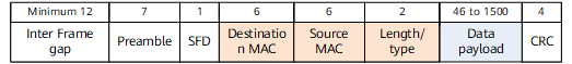
After CAR is performed, the Inter frame gap, Preamble, and SFD fields are not involved in the bandwidth calculation.