Understanding Multicast NAT's Clean Switching
Figure 1 shows multicast NAT's clean switching.
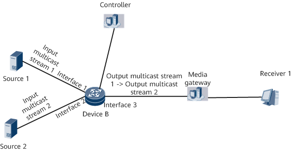
- Input multicast stream 1 is input to the multicast NAT device (DeviceB) and is translated into output multicast stream 1. The characteristics of the multicast stream can change or not.
- Input multicast stream 2 is input to the multicast NAT device (DeviceB) but is not translated into an output multicast stream. DeviceB receives both input multicast streams 1 and 2, but outputs only output multicast stream 1.
- After receiving a clean switching instruction from the controller, DeviceB outputs multicast stream 2. During the switching, the media gateway detects that no excess packets are received or no packet loss occurs through the stream characteristics. Receiver 1 does not detect erratic display or frame freezing.
Definition of Multicast NAT's Clean Switching
Video switching refers to the process of switching from a video signal source to another video signal source instantaneously. Specifically, on the TV screen, a picture is quickly switched to another picture, for example, switching between video sources output by multiple cameras, or switching between video sources of multiple programs. The basic requirements of video switching are frame precision, clean switching, frame synchronization for output signals before and after switching, and no picture damage. Clean switching ensures that no black screen, erratic display, or frame freezing occurs when the receive end receives traffic during the switching of two video streams.
Fundamentals of Multicast NAT's Clean Switching
- The SSRC field is used to identify a synchronization source. The source of an RTP packet is identified by the 32-bit SSRC identifier in the RTP header so that it does not depend on the network address. All packets from a synchronization source form part of the same timing and SN space, and a receiver groups packets by synchronization source for playback. In clean switching, this field can be configured to ensure that two synchronization sources have different SSRC identifiers. A receiver distinguishes the sources based on the SSRC identifiers.
- The SN field is used to identify the sequence number of an RTP packet sent by a sender. Each time a packet is sent, the sequence number increases by 1. This field can be used to check packet loss. It can also be used to reorder data if network jitter occurs. The pre- and post-switching SNs must be consecutive. In clean switching, this field can be configured to check whether packet disorder or packet loss occur during the switching.
- When the length of an SN exceeds 16 bits, overflow occurs. An EXT-SN can be used to resolve this issue. The SN is equivalent to the lower 16 bits of a 32-bit integer, and the EXT-SN is equivalent to the upper 16 bits of the 32-bit integer. If the length of the SN is greater than 16 bits (that is, 65535), the EXT-SN increases by 1. This field can be configured to check whether an abnormal carry occurs on the SN. An abnormal carry means that a carry occurs when the SN is not greater than 65535.
In some scenarios, the system checks only some of the SN, EXT-SN, and SSRC fields during the switching. Which fields need to be checked depends on the video stream format and media gateway.
Process of Multicast NAT's Clean Switching
Multicast Stream Characteristics |
Input Multicast Stream 1 |
Input Multicast Stream 2 |
Output Multicast Stream 1 |
Output Multicast Stream 2 |
|---|---|---|---|---|
Source MAC address |
1111–1111–1111 |
2222–2222–2222 |
1111–1111–1111 |
2222–2222–2222 |
Source IP address |
10.10.10.10 |
12.12.12.12 |
10.10.10.10 |
12.12.12.12 |
Source UDP port number |
8000 |
8006 |
8000 |
8006 |
Destination IP address |
239.0.0.1 |
239.1.0.2 |
239.0.0.1 |
239.1.0.2 |
Destination UDP port number |
10000 |
10002 |
10000 |
10002 |
- Input multicast stream 1 is matched based on two-level traffic policies on interface 1. The level-1 traffic policy matches the source MAC address of input multicast stream 1, and a traffic behavior is associated with the level-2 traffic policy. The level-2 traffic policy matches the source IP address, destination IP address, and UDP port number of input multicast stream 1, and a traffic behavior is associated with a multicast NAT instance. The mapping between input multicast stream 1 and the multicast NAT instance is established using the two-level traffic policies.
- Input multicast stream 2 is matched based on two-level traffic policies on interface 1. The level-1 traffic policy matches the source MAC address of input multicast stream 1, and a traffic behavior is associated with the level-2 traffic policy. The level-2 traffic policy matches the source IP address, destination IP address, and UDP port number of input multicast stream 2, and a traffic behavior is associated with a multicast NAT instance. The mapping between input multicast stream 2 and the multicast NAT instance is established using the two-level traffic policies.
- Multicast stream translation rules are configured on a specified outbound interface (interface 3) to translate or not to translate the characteristics of output multicast stream 1. Output multicast stream 1 is bound to the multicast NAT instance, thereby implementing the translation between the input and output multicast streams.
- After the controller delivers a clean switching instruction to DeviceB, DeviceB unbinds output multicast stream 1 from the multicast NAT instance, and binds output multicast stream 2 to the multicast NAT instance. This implements clean switching.