L2TP/GTP Scenario
About L2TP Tunnels
The Layer 2 Tunneling Protocol (L2TP) allows enterprise users, small-scale ISPs, and mobile office users to access a VPN over a public network (PSTN/ISDN) and the access network.
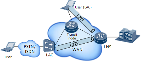
An L2TP tunnel involves three node types, as shown in Figure 1:
L2TP Access Concentrator (LAC): a network device capable of PPP and L2TP. It is usually an ISP's access device that provides access services for users over the PSTN/ISDN. An LAC uses L2TP to encapsulate the packets received from users before sending them to an LNS and decapsulates the packets received from the LNS being sending them to the users.
- L2TP Network Server (LNS): a network device that accepts and processes L2TP tunnel requests. Users can access VPN resources after they have been authenticated by the LNS. An LNS and an LAC are two endpoints of an L2TP tunnel. The LAC initiates an L2TP tunnel, whereas the LNS accepts L2TP tunnel requests. An LNS is usually deployed as an enterprise gateway or a PE on an IP public network.
- Transit node: a transmission device on the transit network between an LAC and an LNS. Various types of networks can be used as the transit networks, such as IP or MPLS networks.
Two Types of L2TP Traffic
L2TP Traffic has two types:
Control message: is used to establish, maintain or tear down the L2TP tunnel and sessions. The format of L2TP control message is shown as Figure 2.
If the transit nodes of L2TP tunnel use per-packet load balancing, the L2TP control messages may arrive out of order, this may result in the failure of L2TP tunnel establishment.
Data message: is used to transmit PPP frames over L2TP tunnel. The data message is not retransmitted if lost. The format of L2TP data message is shown as Figure 3.

Hash Result of L2TP Traffic
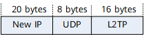
In L2TP scenarios, the traffic are added a new IP header by LAC node. The source IP address of the new IP header is the L2TP tunnel address of LAC node, and destination address of the new IP header is the L2TP tunnel address of the remote LNS. That is, the source IP address and destination IP address of the new IP header is unique. Therefore, the L2TP traffic is belongs to the same flow. The load balancing result depends on the number of the L2TP tunnels (Tunnel ID) or sessions (Session ID) carrying the traffic. The more L2TP tunnels or sessions, the better result of load balancing.
GTP Scenario
Load balancing in the GTP scenario is similar to that in the L2TP scenario. The transit node performs load balancing based on the IP address in the IP header and the tunnel endpoint identifier (TEID) in the GTP header.