MPLS MTU Fragmentation
MPLS MTU Definition
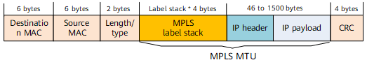
The Multiprotocol Label Switching (MPLS) MTU defines the maximum number of bytes in a labeled packet that an MPLS device can forward without fragmenting the packet. In NetEngine 8000 F, the MPLS MTU is the total length of the following fields:
- MPLS label stack
- IP header
- IP payload
MPLS MTU Usage Scenarios
On NetEngine 8000 F, the MPLS MTU takes effect only on Layer 3 traffic traveling from IP networks to MPLS tunnels. The MPLS packets on which a specified MPLS MTU takes effect must contain labels next to the IP headers. MPLS MTU usage scenarios are as follows:
- MPLS L3VPN scenario, the traffic forwarding from User-to-network interface (UNI) Network-to-network interface (NNI).
- IP traffic on PEs or Ps is directed into LSPs using policy-based routing (PBR), the redirection function, static routes, Interior Gateway Protocol (IGP) shortcuts, and forwarding adjacency.
- Packets originate from the control plane and are directed to LSPs. For example, run the ping -vpn-instance or ping lsp command is executed on the device, the device originates ICMP Request messages. These messages are IP packets and will be sent to MPLS tunnels.
MPLS MTU Value Selection
The basic MPLS MTU formula is:
MPLS MTU = IP MTU + Number of labels x 4 bytes
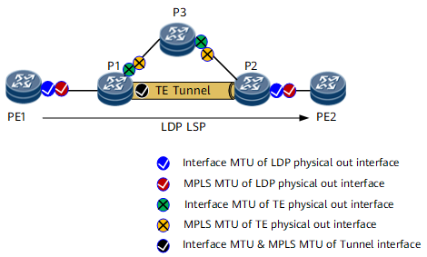
On NetEngine 8000 F, the following parameters may affect MPLS MTU selection:
Configured interface MTU on the physical outbound interface
Configured MPLS MTU on the physical outbound interface
PMTU negotiated by LDP signalling (for details about this parameter, see chapter Protocols MTU Negotiation)
PMTU negotiated by RSVP-TE signalling (for details about this parameter, see chapter Protocols MTU Negotiation)
Configured interface MTU on the tunnel interface
For detailed rules of MPLS MTU Value Selection, see Table 1.
Scenarios |
Parameters which may affect MPLS MTU value selection ("Y" indicates affect, "N" indicates no affect, the smallest value among the affecting parameters is selected as the MPLS MTU) |
||||
|---|---|---|---|---|---|
interface MTU on the physical out interface |
MPLS MTU on the physical out interface |
PMTU negotiated by LDP signalling |
PMTU negotiated by RSVP-TE signalling |
interface MTU on the tunnel interface |
|
LDP LSP |
Y |
Y |
Y |
N |
N |
MPLS-TE |
Y |
Y |
N |
Y |
N |
LDP over TE |
Y |
Y |
Y |
N |
Y |
NOTE:
In LDP over TE scenario, interface MTU on the tunnel interface affects MPLS MTU value selection, because the LDP LSP is over TE tunnel and the TE tunnel interface is an out interface of the LDP LSP.
|
|||||
According to the above rules, the selected MPLS MTU on NetEngine 8000 F is impossible larger than the physical interface MTU. Therefore, the size of the MPLS-labeled packets are less than or equal to the physical interface MTU and will not be discarded by the local device if DF=0.
Fragmentation Implementation for IP Packets That Enter MPLS Tunnels
- if DF=0, the packet is fragmented. Each fragment (including the IP header and label) is less than or equal to the MPLS MTU value.
- if DF=1, the packet is discarded and an ICMP Datagram Too Big message is sent to the source end.
For the MPLS packets received from the physical interface of the NetEngine 8000 F device, different board types may have different MPLS MTU fragmentation modes, as shown in [xref]Target does not exist.
Fragmentation mode |
Board Type |
MPLS Fragmentation Rules on the Forwarding Plane |
|---|---|---|
Figure 2 Mode A
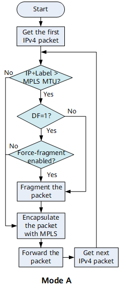 |
- |
MPLS fragmentation is implemented only on the ingress for IP packets entering an MPLS tunnel. When the total length of the IP datagram and label of a packet exceeds a specified MPLS MTU, and DF is set to 0, the IP datagram is fragmented. Each fragment is attached one or more MPLS labels and then forwarded. When the total length of the IP datagram and label of a packet exceeds a specified MPLS MTU, and DF is set to 1,
|