NetEngine 8000 F2A-8K36H
Overview
| Description | Part Number | Model | First Supported Version | Remarks |
|---|---|---|---|---|
| NetEngine 8000 F2A-8K36H Integrated Chassis Components(Port-side Intake) | 02354GTC | CR8P0BKP03C0 | V800R021C00 | - |
| NetEngine 8000 F2A-8K36H Integrated Chassis Components(Port-side Exhaust) | 02354GTD | CR8P0BKP03C1 | V800R021C00 | - |
Appearance

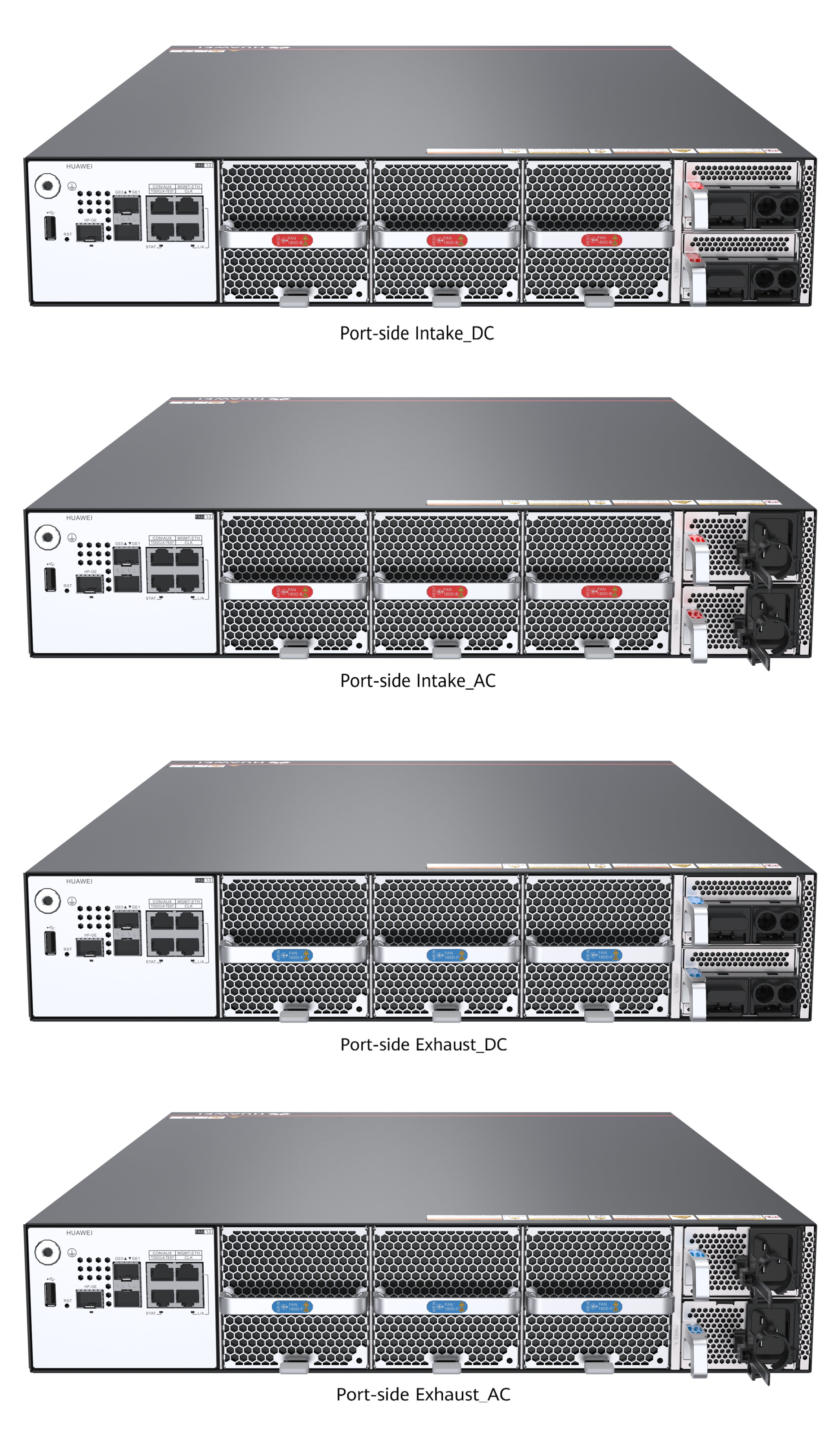

Figures in the document are for reference only, and the actual appearance of the devices may vary depending on the exact device model.
A chassis that adopts port-side air intake can house only power modules and fan modules with the same air intake mode.
Similarly, a chassis that adopts port-side air exhaust can house only power modules and fan modules with the same air exhaust mode.
Version Mapping
| Product Model | Part Number | Model | Description | First Supported Version |
|---|---|---|---|---|
| CR8P0BKP03C0 | 82402763 | CR8S0F2AE1CA | NetEngine 8000 F2A-8K36H 50G Port Enable RTU(per 50G) | V800R021C00 |
| CR8P0BKP03C0 | 88036YBU | CR8S0F2AE1C1 | NetEngine 8000 F2A-8K36H 50G Port Enable RTU(per 50G) | V800R021C00 |
| CR8P0BKP03C0 | 88037AJG | CR8S0F2AE1C3 | NetEngine 8000 F2A-8K36H 100G Upgrade to 400G Port Enable RTU(per 400G) | V800R021C00 |
| CR8P0BKP03C0 | 88037AJP | CR8S0F2AE1C3 | NetEngine 8000 F2A-8K36H 100G Upgrade to 200G Port Enable RTU(per 200G) | V800R021C00 |
| CR8P0BKP03C0 | 88037AJH | CR5S5KNBSL5P | NetEngine 8000 F2A-8K36H 200G Upgrade to 400G Port Enable RTU(per 400G) | V800R021C00 |
| CR8P0BKP03C0 | 88037ATA | CR8S0F1AE1CL | NetEngine 8000 F Series Private Line Slicing RTU(per 16-slice RTU) | V800R021C00 |
| CR8P0BKP03C1 | 82402763 | CR8S0F2AE1CA | NetEngine 8000 F2A-8K36H 50G Port Enable RTU(per 50G) | V800R021C00 |
| CR8P0BKP03C1 | 88036YBU | CR8S0F2AE1C1 | NetEngine 8000 F2A-8K36H 50G Port Enable RTU(per 50G) | V800R021C00 |
| CR8P0BKP03C1 | 88037AJG | CR8S0F2AE1C3 | NetEngine 8000 F2A-8K36H 100G Upgrade to 400G Port Enable RTU(per 400G) | V800R021C00 |
| CR8P0BKP03C1 | 88037AJP | CR8S0F2AE1C3 | NetEngine 8000 F2A-8K36H 100G Upgrade to 200G Port Enable RTU(per 200G) | V800R021C00 |
| CR8P0BKP03C1 | 88037AJH | CR5S5KNBSL5P | NetEngine 8000 F2A-8K36H 200G Upgrade to 400G Port Enable RTU(per 400G) | V800R021C00 |
| CR8P0BKP03C1 | 88037ATA | CR8S0F1AE1CL | NetEngine 8000 F Series Private Line Slicing RTU(per 16-slice RTU) | V800R021C00 |
For details about how to use the RTU, see "License Usage Guide".
Slot Layout
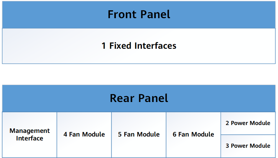
| Slot Type | Slot ID | Slot Direction | Remarks |
|---|---|---|---|
| IPU | 1 | - | - |
| POWER | 2 | - | - |
| POWER | 3 | - | - |
| FAN | 4 | - | - |
| FAN | 5 | - | - |
| FAN | 6 | - | - |
Panel
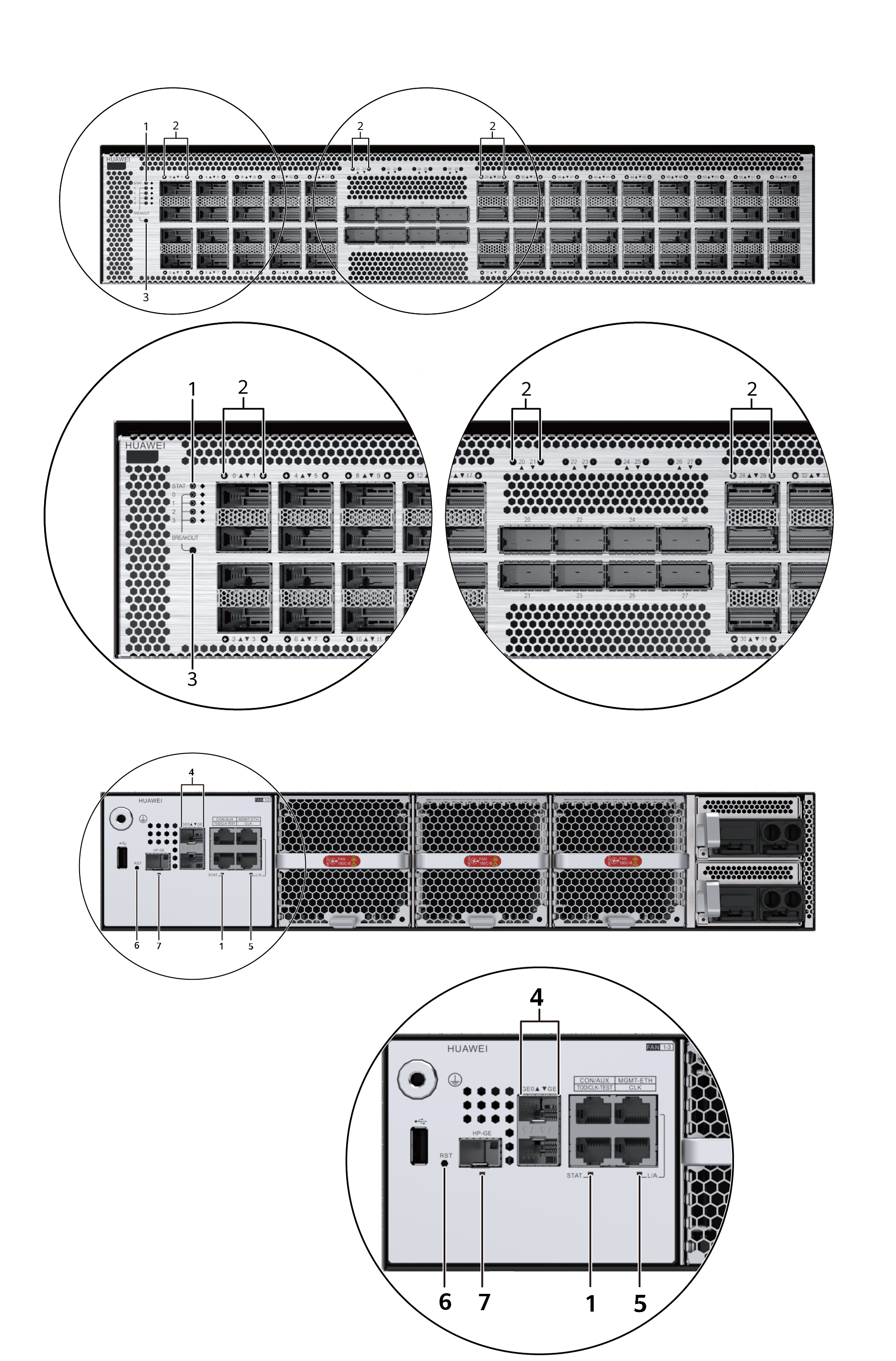
1. Status indicator(STAT) |
2. Port status indicator(0~63) |
3. Breakout channel indicator(Breakout(0~3)) |
4. Port status indicator(GE0,GE1) |
5. Management port status indicator(L/A) |
6. Reset button(RST) |
7. Port status indicator(HP-GE) |
- |
| Silkscreen | Name | Color | Status | Description |
|---|---|---|---|---|
| STAT | Status indicator | Green | Steady on | The device is working properly. |
| Red | Steady on | An alarm is generated. | ||
| Green | Blinking | The card is being registered. | ||
| Orange | Blinking | The password and configuration on the card are being cleared. | ||
| - | Off | The system is not powered on or registered. | ||
| L/A (MGMT-ETH) | Management Ethernet port status indicator | Green | Steady on | The link is up. |
| Green | Blinking | Data is being transmitted or received. | ||
| - | Off | The link is down. | ||
| Breakout (0–3) | Breakout channel indicator | Green | Blinking | Each breakout indicator for channels 0–3 turns on for 5 seconds in sequence to indicate the status of the corresponding channel. |
| - | Off | No data is being transmitted or received over this channel. | ||
| GE0, GE1 | Port status indicator | Green | Steady on | The link is up. |
| Green | Blinking | Data is being transmitted or received. | ||
| - | Off | The link is down. | ||
| HP-GE | Green | Steady on | The link is up. | |
| Green | Blinking | Data is being transmitted or received. | ||
| - | Off | The link is down. | ||
| 0–63 | Green | Steady on | The link is up. | |
| Green | Blinking | Data is being transmitted or received. | ||
| - | Off | The link is down. |
| Silkscreen | Name | Description |
|---|---|---|
| RST | Reset button | You can press the RST button to reset the NE or restore the factory defaults of the NE. The procedure is as follows: To reset the NE, press the RST button and release it. To restore factory settings, press and hold down the RST button. This operation will clear the NE database and system parameter configurations and cannot be restored. Exercise caution when you perform the following operations: 1. Press the RST button to restart the NE. 2. When the STAT indicator blinks green (the blinking frequency is about 250 ms and the time window is about 15 seconds), press and hold down the RST button. 3. Wait for no longer than 2 minutes till the STAT indicators blink orange (the time window is 5 seconds). Then release the RST button immediately. NOTE:
1. When you press the RST button to clear the configuration file, the original configuration file will be cleared. You are advised to periodically back up the configuration file. 2. When pressing the RST button to clear the configuration file, you only need to pay attention to the STAT indicator. Other indicators may vary depending on the product model. |
| Port | Connector Type | Description | Available Components |
|---|---|---|---|
| 0–19 | QSFP28 | Port for inputting and outputting 100GE/50GE/40GE optical signals | |
| 20–27 | QSFPDD | Port for inputting and outputting 400GE/100GE/50GE/40GE optical signals NOTE:
1. Port 20 shares 400G bandwidth with ports 8, 9, and 12. Port 21 shares 400G bandwidth with ports 10, 11, and 14. Port 22 shares 400G bandwidth with ports 13, 16, and 17. Port 23 shares 400G bandwidth with ports 15, 18, and 19. 2. Port 24 shares 400G bandwidth with ports 28 and 29. Port 25 shares 400G bandwidth with ports 30 and 31. Port 26 shares 400G bandwidth with ports 32 and 33. Port 27 shares 400G bandwidth with ports 34 and 35. 3. Ports 20–25 support FlexE. |
400Gbps QSFP-DD Optical Module 50Gbps QSFP28 BIDI Optical Module NOTE:
1.Devices that work in port-side air exhaust mode do not support 40 km and 80 km 400 Gbit/s optical modules. 2.When an 80 km QSFP-DD optical module is applied, the optical amplifier is required. |
| 28–63 | QSFP28 | Port for inputting and outputting 100GE/50GE/40GE optical signals. NOTE:
Ports 36-51 support 4*25G and 4*10G breakout optical module. |
|
| GE0/GE1 | SFP | Cascading port used for control panel expansion in scenarios like virtual cluster (reserved) | Reserved |
| HP-GE | SFP | High-precision clock port (reserved) | Reserved |
| MGMT-ETH | RJ45 | Port for connecting to the NMS workstation | Category 5 enhanced shielded twisted pair |
| Console/AUX hybrid | RJ45 | Port for connecting to the console for onsite system configuration. The default baud rate is 9600 bit/s. (The AUX hybrid port is reserved.) | 8-core shielded cable |
| TOD clock | RJ45 | Port for inputting and outputting one-channel 1PPS+TOD time signals or one-channel DCLS signals | 120-ohm clock cable |
| CLK | RJ45 | Port for inputting and outputting 2 Mbit/s or 2 MHz clock signals | 120-ohm clock cable |
| USB | Type A | USB port (reserved) | N/A |
Interface Numbering Rules
On the NetEngine 8000 F2A-8K36H, an interface is numbered in the format of "slot number/subcard number/port number". The following part describes the details:
Slot number
The slot number of NetEngine 8000 F2A-8K36H is always 0.
Subcard number
The NetEngine 8000 F2A-8K36H does not support subcards. Therefore, the subcard number of the 8000 F2A-8K36H is fixed as 1.
Port number
The port numbers of service interfaces on the NetEngine 8000 F2A-8K36H begin with 0. Port numbering depends on the number of interfaces on the NetEngine 8000 F2A-8K36H.
Ports
Port Number |
Port Type |
|---|---|
0 to 19, 28 to 63 |
100GE/50GE/40GE |
20 to 27 |
400GE/100GE/50GE/40GE |
NOTE:
|
|
Labels
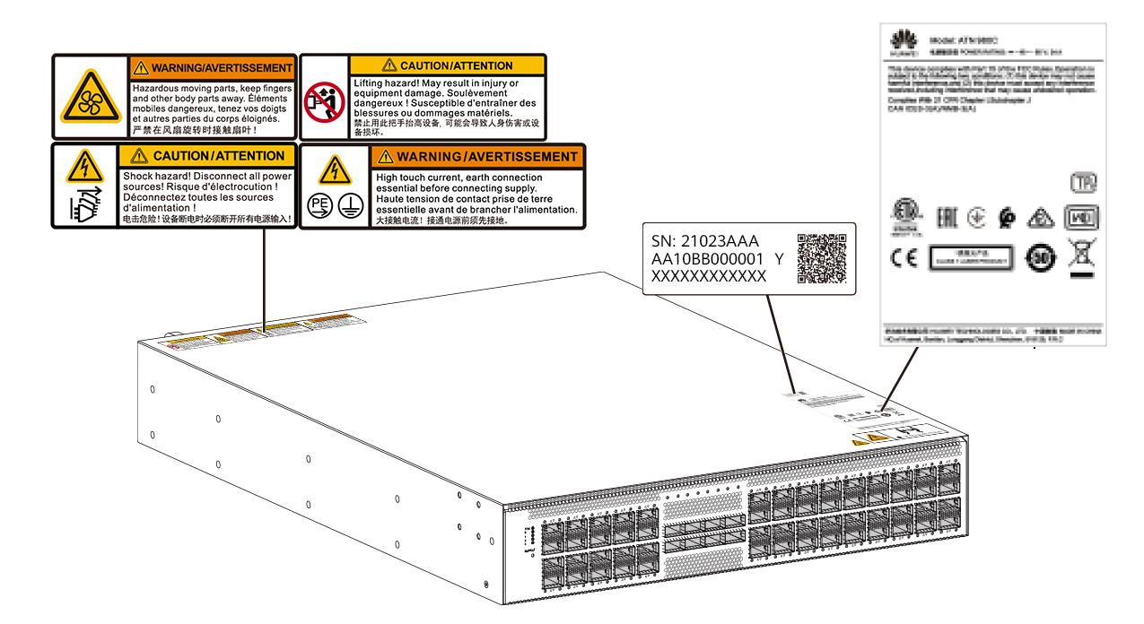
Figure |
Label Name |
Description |
|---|---|---|
|
Chassis bar code label |
The bar code will be retrieved by the device as the equipment serial number (ESN). |
|
Warning and caution |
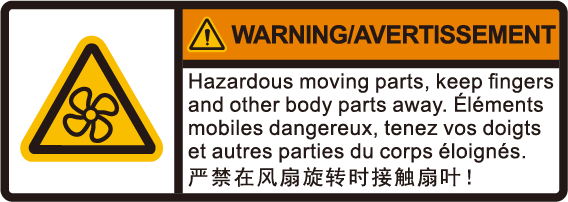
Do not touch the fan when the fan is rotating. |
|
Do not use this handle to lift the device. May result in injury or equipment damage. |
|
|
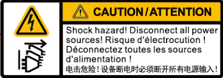
This device has more than one power input. Disconnect all power inputs to power off this device. |
|
|
High touch current, earth connection essential before connecting supply. |
|
|
Product nameplate label |
The label suggests the product name, certification and qualification. |
Technical Specifications
| Item | Specification |
|---|---|
| Dimensions without packaging (H x W x D) [mm(in.)] | 86.1 mm x 442 mm x 600 mm (3.39 in. x 17.4 in. x 23.62 in.) |
| Dimensions with packaging (H x W x D) [mm(in.)] | 280 mm x 660 mm x 875 mm (11.02 in. x 25.98 in. x 34.45 in.) |
| Chassis height [U] | 2 U |
| Weight without packaging (base configuration) [kg(lb)] | 18 kg (39.68 lb) |
| Weight without packaging (full configuration) [kg(lb)] | DC: 21 kg (46.3 lb) AC: 20.5 kg (45.19 lb) |
| Weight with packaging (full configuration) [kg(lb)] | DC: 31.5 kg (69.45 lb) AC: 30 kg (66.14 lb) |
| Typical power consumption (with configuration) [W] | 1100 W |
| Typical heat dissipation (with configuration) [BTU/hour] | 3574 BTU/hour |
| CPU | 8core@2.3GHz |
| SDRAM | 16 GB |
| Flash memory | 64 MB |
| Storage | 8 GB |
| Power supply mode |
|
| Maximum number of power chassis inputs | 2 |
| Rated input voltage [V] | DC: –48 V to –60 V AC: 100 V to 130 V (dual-live wire)/200 V to 240 V HVDC: 190 V–240 V |
| Input voltage range [V] | DC: –40 V to –72 V AC: 90 V–290 V HVDC: 190 V–290 V |
| Maximum input current [A] | DC: 50A AC/HVDC: 16A |
| Rated output power [W] | DC: 2200 W AC: 3000 W (input : 200 VAC–290 VAC/200 VDC–290 VDC) 2800 W (input : 176 VAC–200 VAC/190 VDC–200 VDC) |
| Front-end circuit breaker/fuse [A] | DC : >=50 AC : >=16 |
| Heat dissipation mode | Air cooling |
| Airflow direction | Front to back: port-side air intake |
| Noise at normal temperature (acoustic power) [dB(A)] | < 78 dBA |
| Number of slots | 6 |
| Number of service board slots | 1 |
| Switching capacity | 13.6 Tbps |
| Redundant power supply | 1+1 |
| Redundant fans | 2+1, normal operation in a short term when a single fan module fails at the ambient temperature of 40°C (104°F) |
| Long-term operating temperature [°C(°F)] | Port-side air intake: –5°C to +45°C (23°F to 113°F) |
| Restriction on the operating temperature variation rate [°C(°F)] | ≤ 30°C/hour (86°F/hour) |
| Storage temperature [°C(°F)] | –40°C to +70°C (–40°F to +158°F) |
| Long-term operating relative humidity [RH] | 5% to 90% RH, non-condensing |
| Short-term operating relative humidity [RH] | 5% to 95% RH, non-condensing |
| Storage relative humidity [RH] | 5% to 95% RH, non-condensing |
| Long-term operating altitude [m(ft.)] | < 4000 m (< 13123.4 ft.) |
| Storage altitude [m(ft.)] | < 5000 m (< 16404.2 ft.) |
| Breakout supported | Supported |
| Interface rate auto-sensing supported | Supported |
| Item | Specification |
|---|---|
| Dimensions without packaging (H x W x D) [mm(in.)] | 86.1 mm x 442 mm x 600 mm (3.39 in. x 17.4 in. x 23.62 in.) |
| Dimensions with packaging (H x W x D) [mm(in.)] | 280 mm x 660 mm x 875 mm (11.02 in. x 25.98 in. x 34.45 in.) |
| Chassis height [U] | 2 U |
| Weight without packaging (base configuration) [kg(lb)] | 18 kg (39.68 lb) |
| Weight without packaging (full configuration) [kg(lb)] | DC: 21 kg (46.3 lb) AC: 20.5 kg (45.19 lb) |
| Weight with packaging (full configuration) [kg(lb)] | DC: 31.5 kg (69.45 lb) AC: 30 kg (66.14 lb) |
| Typical power consumption (with configuration) [W] | 1100 W |
| Typical heat dissipation (with configuration) [BTU/hour] | 3574 BTU/hour |
| CPU | 8core@2.3GHz |
| SDRAM | 16 GB |
| Flash memory | 64 MB |
| Storage | 8 GB |
| Power supply mode |
|
| Maximum number of power chassis inputs | 2 |
| Rated input voltage [V] | DC: –48V to –60V AC: 100 V to 130 V (dual-live wire)/200 V to 240 V HVDC: 190V–240V |
| Input voltage range [V] | DC: –40V to–72V AC: 90V–290V HVDC: 190V–290V |
| Maximum input current [A] | DC: 50A AC/HVDC: 16A |
| Rated output power [W] | DC:2200W AC:3000W(input : 200Vac-290Vac/200Vdc-290Vdc) 2800W(input : 176Vac-200Vac/190Vdc-200Vdc) |
| Front-end circuit breaker/fuse [A] | DC : >=50 AC : >=16 |
| Heat dissipation mode | Air cooling |
| Airflow direction | Back to front: port-side air exhaust |
| Noise at normal temperature (acoustic power) [dB(A)] | < 78 dBA |
| Number of slots | 6 |
| Number of service board slots | 1 |
| Switching capacity | 13.6 Tbps |
| Redundant power supply | 1+1 |
| Redundant fans | 2+1, normal operation in a short term when a single fan module fails at the ambient temperature of 40°C (104°F) |
| Long-term operating temperature [°C(°F)] | Port-side air exhaust: 0°C to 40°C (32°F to 104°F) |
| Restriction on the operating temperature variation rate [°C(°F)] | ≤ 30°C/hour (86°F/hour) |
| Storage temperature [°C(°F)] | –40°C to +70°C (–40°F to +158°F) |
| Long-term operating relative humidity [RH] | 5% to 90% RH, non-condensing |
| Short-term operating relative humidity [RH] | 5% to 95% RH, non-condensing |
| Storage relative humidity [RH] | 5% to 95% RH, non-condensing |
| Long-term operating altitude [m(ft.)] | < 4000 m (< 13123.4 ft.) |
| Storage altitude [m(ft.)] | < 5000 m (< 16404.2 ft.) |
| Breakout supported | Supported |
| Interface rate auto-sensing supported | Supported |


