Example for Configuring Local Proxy ARP
This section provides an example for configuring local proxy ARP to allow two isolated member interfaces in a BD to intercommunicate in an EVC scenario.
Networking Requirements
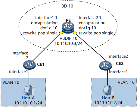
In the EVC model, after receiving packets, the member interfaces of a BD broadcast these packets in the BD. To reduce broadcast operations, network administrators usually configure split horizon on the member interfaces that do not need to intercommunicate to isolate these member interfaces.
As shown in Figure 1, network administrators have configured split horizon on PEs to isolate Host A and Host B. As user services develop, however, Host A and Host B need to intercommunicate some day. To resolve this problem, network administrators need to enable local proxy ARP on VBDIF interfaces to allow Host A and Host B to intercommunicate.

Precautions
After local proxy ARP is enabled, all users in the BD can intercommunicate. To allow only specific users in a BD to intercommunicate, running the undo split-horizon enable command on these member interfaces that need intercommunicate to disable split horizon is recommended.
Configuration Roadmap
The configuration roadmap is as follows:
Configure Layer 2 forwarding on the CE.
- Create a VLAN on the CE and add the downstream interface of the CE to the VLAN.
- Configure Layer 2 forwarding on the CE so that the CE send single-tagged packets to the PE.
- Create an EVC model on the PE.
- Configure a BD to forward services.
- Create a Layer 2 sub-interface, add it to the BD, and configure traffic encapsulation on the downstream interface to ensure that services access the service access point.
- Configure split horizon in the BD to isolate Host A and Host B.
- Configure local proxy ARP on the PE.
- Create a VBDIF interface and assign an IP address to it.
- Enable local proxy ARP to allow Host A and Host B to intercommunicate.
Data Preparation
- User VLAN ID
- Number of interfaces that connect the CEs and connect the CE to PE
- BD ID, traffic encapsulation type, and traffic behavior
- VBDIF interface number and IP address
Procedure
- Configure Layer 2 forwarding on the CE.
# Configure CE1.
<HUAWEI> system-view
[~HUAWEI] sysname CE1
[*HUAWEI] commit
[~CE1] vlan 10
[*CE1-vlan10] quit
[*CE1] interface gigabitethernet 0/1/1
[*CE1-GigabitEthernet0/1/1] undo shutdown
[*CE1-GigabitEthernet0/1/1] portswitch
[*CE1-GigabitEthernet0/1/1] port link-type access
[*CE1-GigabitEthernet0/1/1] port default vlan 10
[*CE1-GigabitEthernet0/1/1] quit
[*CE1] interface gigabitethernet 0/1/2
[*CE1-GigabitEthernet0/1/2] undo shutdown
[*CE1-GigabitEthernet0/1/2] portswitch
[*CE1-GigabitEthernet0/1/2] port link-type trunk
[*CE1-GigabitEthernet0/1/2] port trunk allow-pass vlan 10
[*CE1-GigabitEthernet0/1/2] commit
[~CE1-GigabitEthernet0/1/2] quit
# Configure CE2.
<HUAWEI> system-view
[~HUAWEI] sysname CE2
[*HUAWEI] commit
[~CE2] vlan 10
[*CE2-vlan10] quit
[*CE2] interface gigabitethernet 0/1/1
[*CE2-GigabitEthernet0/1/1] undo shutdown
[*CE2-GigabitEthernet0/1/1] portswitch
[*CE2-GigabitEthernet0/1/1] port link-type access
[*CE2-GigabitEthernet0/1/1] port default vlan 10
[*CE2-GigabitEthernet0/1/1] quit
[*CE2] interface gigabitethernet 0/1/2
[*CE2-GigabitEthernet0/1/2] undo shutdown
[*CE2-GigabitEthernet0/1/2] portswitch
[*CE2-GigabitEthernet0/1/2] port link-type trunk
[*CE2-GigabitEthernet0/1/2] port trunk allow-pass vlan 10
[*CE2-GigabitEthernet0/1/2] commit
[~CE2-GigabitEthernet0/1/2] quit
- Create an EVC model on the PE.
# Create a BD.
<HUAWEI> system-view
[~HUAWEI] sysname PE
[*HUAWEI] commit
[~PE] bridge-domain 10
[*PE-bd10] quit
# Create a Layer 2 sub-interface, add it to the BD, and configure traffic encapsulation on the downstream interface.
[*PE] interface gigabitethernet 0/1/1
[*PE-GigabitEthernet0/1/1] undo shutdown
[*PE-GigabitEthernet0/1/1] quit
[*PE] interface gigabitethernet 0/1/1.1 mode l2
[*PE-GigabitEthernet0/1/1.1] encapsulation dot1q vid 10
[*PE-GigabitEthernet0/1/1.1] rewrite pop single
[*PE-GigabitEthernet0/1/1.1] bridge-domain 10
[*PE-GigabitEthernet0/1/1.1] commit
[~PE-GigabitEthernet0/1/1] quit
[~PE] interface gigabitethernet 0/1/2
[~PE-GigabitEthernet0/1/2] undo shutdown
[*PE-GigabitEthernet0/1/2] quit
[*PE] interface gigabitethernet 0/1/2.1 mode l2
[*PE-GigabitEthernet0/1/2.1] encapsulation dot1q vid 10
[*PE-GigabitEthernet0/1/2.1] rewrite pop single
[*PE-GigabitEthernet0/1/2.1] bridge-domain 10
[*PE-GigabitEthernet0/1/2.1] commit
[~PE-GigabitEthernet0/1/2] quit
# Ping the IP address of Host B on Host A. The ping operation succeeds.c:\>ping 10.110.10.2 Pinging 10.110.10.2 with 32 bytes of data: Reply from 10.110.10.2: bytes=32 time<1ms TTL=128 Reply from 10.110.10.2: bytes=32 time<1ms TTL=128 Reply from 10.110.10.2: bytes=32 time<1ms TTL=128 Reply from 10.110.10.2: bytes=32 time<1ms TTL=128 Ping statistics for 10.110.10.2: Packets: Sent = 4, Received = 4, Lost = 0 <0% loss>, Approximate round trip times in mill-seconds: Minimum = 0ms, Maximum = 0ms, Average = 0ms# Configure split horizon in the BD.
[~PE] bridge-domain 10 [*PE-bd-10] split-horizon enable [*PE-bd-10] quit [*PE] commit
# Ping the IP address of Host B on Host A. The ping operation fails.c:\>ping 10.110.10.2 Pinging 10.110.10.2 with 32 bytes of data: Request timed out. Request timed out. Request timed out. Request timed out. Ping statistics for 10.110.10.2: Pacets: Sent = 4, Received = 0, Lost = 4 <100% loss>, - Configure local proxy ARP on the PE.
# Create a VBDIF interface and assign an IP address to it.
[~PE] interface vbdif 10 [*PE-Vbdif10] ip address 10.110.10.3 255.255.255.0
# Enable local proxy ARP.
[*PE-Vbdif10] arp-proxy local enable [*PE-Vbdif10] commit
- Verify the configuration.
After the preceding configuration is complete, ping the IP address of Host B on Host A. The ping operation succeeds.
c:\>ping 10.110.10.2 Pinging 10.110.10.2 with 32 bytes of data: Reply from 10.110.10.2: bytes=32 time<1ms TTL=128 Reply from 10.110.10.2: bytes=32 time<1ms TTL=128 Reply from 10.110.10.2: bytes=32 time<1ms TTL=128 Reply from 10.110.10.2: bytes=32 time<1ms TTL=128 Ping statistics for 10.110.10.2: Packets: Sent = 4, Received = 4, Lost = 0 <0% loss>, Approximate round trip times in mill-seconds: Minimum = 0ms, Maximum = 0ms, Average = 0msThe display bridge-domain command output shows information about the BD to which the Layer 2 sub-interface is added.
[~PE] display bridge-domain
The total number of bridge-domains is : 1
--------------------------------------------------------------------------------
MAC_LRN: MAC learning;         STAT: Statistics;         SPLIT: Split-horizon;
BC: Broadcast;                 MC: Unknown multicast;    UC: Unknown unicast;
*down: Administratively down;  FWD: Forward;             DSD: Discard;
--------------------------------------------------------------------------------

BDID  State MAC-LRN STAT    BC  MC  UC  SPLIT   Description
--------------------------------------------------------------------------------
10    up    enable  disable FWD FWD FWD enable
Configuration Files
PE configuration file
#
sysname PE
#
vlan batch 10
#
bridge-domain 10
 split-horizon enable
#
interface Vbdif10
 undoshutdown
 ip address 10.110.10.3 255.255.255.0
 arp-proxy local enable
#
interface GigabitEthernet0/1/1
 undo shutdown
#
interface GigabitEthernet0/1/1.1 mode l2
 encapsulation dot1q vid 10
 rewrite pop single
 bridge-domain 10
#
interface GigabitEthernet0/1/2
 undo shutdown
#
interface GigabitEthernet0/1/2.1 mode l2
 encapsulation dot1q vid 10
 rewrite pop single
 bridge-domain 10
#
return
CE1 configuration file
#
sysname CE1
#
vlan batch 10
#
interface GigabitEthernet0/1/1
 portswitch
 undo shutdown
 port link-type access
 port default vlan 10
#
interface GigabitEthernet0/1/2
 portswitch
 undo shutdown
 port link-type trunk
 port trunk allow-pass vlan 10
#
return
CE2 configuration file
#
sysname CE1
#
vlan batch 10
#
interface GigabitEthernet0/1/1
 portswitch
 undo shutdown
 port link-type access
 port default vlan 10
#
interface GigabitEthernet0/1/2
 portswitch
 undo shutdown
 port link-type trunk
 port trunk allow-pass vlan 10
#
return