Example for Configuring Sub-Interfaces for Dot1q VLAN Tag Termination to Support BFD
Sub-interfaces for dot1q VLAN tag termination are configured to support BFD on a typical network. In this manner, user packets with one tag can be reliably and stably sent over the network.
Networking Requirements
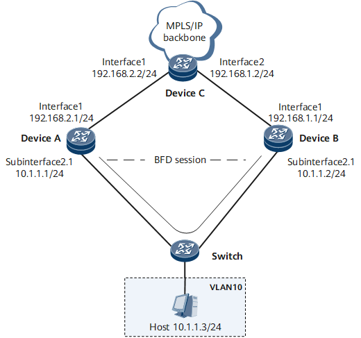
On the network shown in Figure 1, users of VLAN 10 access an ISP network through a default gateway. GE 0/1/8.1 is a sub-interface for dot1q VLAN tag termination on Device A, and GE 0/1/8.1 is a sub-interface for dot1q VLAN tag termination on Device B.
A BFD session is configured on Device A and Device B to monitor the link between Device A and Device B.
VRRP group 1 is configured on Device A and Device B. Device A functions as the master device and Device B functions as the backup device.
VRRP group 1 on Device A and Device B to track the status of the BFD session.

Configuration Roadmap
The configuration roadmap is as follows:
Configure an IGP to implement connectivity between Device A, Device B, and Device C.
Configure the Layer 2 forwarding function on the switch.
Configure sub-interfaces for dot1q VLAN tag termination on Device A and Device B.
Configure a BFD session on Device A and Device B to monitor the link between Device A and Device B.
Configure VRRP group 1 on GE 0/1/8.1 of Device A and GE 0/1/8.1 of Device B. Device A functions as the master device and Device B functions as the backup device.
Data Preparation
To complete the configuration, you need the following data:
VLAN ID of a dot1q VLAN tag termination sub-interface
Name of a BFD session
ID and virtual IP address of a VRRP group
Procedure
- Configure an IGP to implement connectivity between devices.
Assign IP addresses to interfaces as shown in Figure 1. Configure an IGP on Device A, Device B, and Device C. OSPF is used in this example.
# Configure Device A.
<HUAWEI> system-view
[~HUAWEI] sysname DeviceA
[*HUAWEI] commit
[~DeviceA] interface gigabitethernet 0/1/0
[~DeviceA-GigabitEthernet0/1/0] undo shutdown
[*DeviceA-GigabitEthernet0/1/0] ip address 192.168.2.1 24
[*DeviceA-GigabitEthernet0/1/0] quit
[*DeviceA] interface gigabitethernet 0/1/8.1
[*DeviceA-GigabitEthernet0/1/8.1] undo shutdown
[*DeviceA-GigabitEthernet0/1/8.1] ip address 10.1.1.1 24
[*DeviceA-GigabitEthernet0/1/8.1] quit
[*DeviceA] ospf 1
[*DeviceA-ospf-1] area 0
[*DeviceA-ospf-1-area-0.0.0.0] network 192.168.2.0 0.0.0.255
[*DeviceA-ospf-1-area-0.0.0.0] network 10.1.1.0 0.0.0.255
[*DeviceA-ospf-1-area-0.0.0.0] commit
[~DeviceA-ospf-1-area-0.0.0.0] quit
[~DeviceA-ospf-1] quit
# Configure Device B.
<HUAWEI> system-view
[~HUAWEI] sysname DeviceB
[*HUAWEI] commit
[~DeviceB] interface gigabitethernet 0/1/0
[*DeviceB-GigabitEthernet0/1/0] undo shutdown
[*DeviceB-GigabitEthernet0/1/0] ip address 192.168.1.1 24
[*DeviceB-GigabitEthernet0/1/0] quit
[*DeviceB] interface gigabitethernet 0/1/8.1
[*DeviceB-GigabitEthernet0/1/8.1] undo shutdown
[*DeviceB-GigabitEthernet0/1/8.1] ip address 10.1.1.2 24
[*DeviceB-GigabitEthernet0/1/8.1] quit
[*DeviceB] ospf 1
[*DeviceB-ospf-1] area 0
[*DeviceB-ospf-1-area-0.0.0.0] network 192.168.1.0 0.0.0.255
[*DeviceB-ospf-1-area-0.0.0.0] network 10.1.1.0 0.0.0.255
[*DeviceB-ospf-1-area-0.0.0.0] commit
[~DeviceB-ospf-1-area-0.0.0.0] quit
[~DeviceB-ospf-1] quit
# Configure Device C.
<HUAWEI> system-view
[~HUAWEI] sysname DeviceC
[*HUAWEI] commit
[~DeviceC] interface gigabitethernet 0/1/0
[~DeviceC-GigabitEthernet0/1/0] undo shutdown
[*DeviceC-GigabitEthernet0/1/0] ip address 192.168.2.2 24
[*DeviceC-GigabitEthernet0/1/0] quit
[*DeviceC] interface gigabitethernet 0/1/8
[*DeviceC-GigabitEthernet0/1/8] undo shutdown
[*DeviceC-GigabitEthernet0/1/8] ip address 192.168.1.2 24
[*DeviceC-GigabitEthernet0/1/8] quit
[*DeviceC] ospf 1
[*DeviceC-ospf-1] area 0
[*DeviceC-ospf-1-area-0.0.0.0] network 192.168.1.0 0.0.0.255
[*DeviceC-ospf-1-area-0.0.0.0] network 192.168.2.0 0.0.0.255
[*DeviceC-ospf-1-area-0.0.0.0] commit
[~DeviceC-ospf-1-area-0.0.0.0] quit
[~DeviceC-ospf-1] quit
After completing the preceding configuration, run the display ip routing-table command on each Device. The command output shows that OSPF correctly calculates routes between Device A and Device B. Device A and Device B can ping each other.
The command output on Device A is used as an example.
<DeviceA> display ip routing-table
Route Flags: R - relay, D - download to fib, T - to vpn-instance, B - black hole route
------------------------------------------------------------------------------
Routing Table: Public
         Destinations : 7       Routes : 7

Destination/Mask    Proto  Pre  Cost       Flags NextHop         Interface
    192.168.2.0/24  Direct 0    0            D   192.168.2.1     GigabitEthernet0/1/0
    192.168.2.1/32  Direct 0    0            D   127.0.0.1       InLoopBack0
    192.168.1.0/24  OSPF   10   2            D   192.168.2.2     GigabitEthernet0/1/0
       10.1.1.0/24  Direct 0    0            D   10.1.1.1        GigabitEthernet0/1/8.1
       10.1.1.1/32  Direct 0    0            D   127.0.0.1       InLoopBack0
      127.0.0.0/8   Direct 0    0            D   127.0.0.1       InLoopBack0
      127.0.0.1/32  Direct 0    0            D   127.0.0.1       InLoopBack0
[~DeviceA] ping 192.168.1.1
PING 192.168.1.1: 56  data bytes, press CTRL_C to break
    Reply from 192.168.1.1: bytes=56 Sequence=1 ttl=254 time=7 ms
    Reply from 192.168.1.1: bytes=56 Sequence=2 ttl=254 time=1 ms
    Reply from 192.168.1.1: bytes=56 Sequence=3 ttl=254 time=5 ms
    Reply from 192.168.1.1: bytes=56 Sequence=4 ttl=254 time=1 ms
    Reply from 192.168.1.1: bytes=56 Sequence=5 ttl=254 time=8 ms

  --- 192.168.1.1 ping statistics ---
    5 packet(s) transmitted
    5 packet(s) received
    0.00% packet loss
    round-trip min/avg/max = 1/4/8 ms
- Configure the Layer 2 forwarding function on the switch.
<HUAWEI> system-view
[~HUAWEI] sysname Switch
[*HUAWEI] commit
[~Switch] vlan 10
[*Switch-vlan10] port gigabitethernet 0/1/0
[*Switch-vlan10] quit
[*Switch] interface gigabitethernet 0/1/1
[*Switch-GigabitEthernet0/1/1] undo shutdown
[*Switch-GigabitEthernet0/1/1] port trunk allow-pass vlan 10
[*Switch-GigabitEthernet0/1/1] quit
[*Switch] interface gigabitethernet 0/1/2
[*Switch-GigabitEthernet0/1/2] undo shutdown
[*Switch-GigabitEthernet0/1/2] port trunk allow-pass vlan 10
[*Switch-GigabitEthernet0/1/2] commit
[~Switch-GigabitEthernet0/1/2] quit
- Configure a sub-interface for dot1q VLAN tag termination on each Device.
# Configure Device A.
[~DeviceA] interface gigabitethernet 0/1/8.1
[*DeviceA-GigabitEthernet0/1/8.1] encapsulation dot1q-termination
[*DeviceA-GigabitEthernet0/1/8.1] dot1q termination vid 10
[*DeviceA-GigabitEthernet0/1/8.1] commit
# Configure Device B.
[~DeviceB] interface gigabitethernet 0/1/8.1
[*DeviceB-GigabitEthernet0/1/8.1] encapsulation dot1q-termination
[*DeviceB-GigabitEthernet0/1/8.1] dot1q termination vid 10
[*DeviceB-GigabitEthernet0/1/8.1] commit
- Configure a BFD session.
# Configure Device A.
[~DeviceA] bfd
[*DeviceA-bfd] quit
[*DeviceA] bfd atob bind peer-ip default-ip interface gigabitethernet 0/1/8.1
[*DeviceA-bfd-session-atob] discriminator local 1
[*DeviceA-bfd-session-atob] discriminator remote 2
[*DeviceA-bfd-session-atob] dot1q vid 10
[*DeviceA-bfd-session-atob] commit
[~DeviceA-bfd-session-atob] quit
# Configure Device B.
[~DeviceB] bfd
[*DeviceB-bfd] quit
[*DeviceB] bfd atob bind peer-ip default-ip interface gigabitethernet 0/1/8.1
[*DeviceB-bfd-session-atob] discriminator local 2
[*DeviceB-bfd-session-atob] discriminator remote 1
[*DeviceB-bfd-session-atob] dot1q vid 10
[*DeviceB-bfd-session-atob] commit
[~DeviceB-bfd-session-atob] quit
After completing the configuration, run the display bfd session all verbose command. The command output shows that the BFD session is UP. The command output on Device A is used as an example.
[~DeviceA] display bfd session all verbose
(w): State in WTR  (*): State is invalid
--------------------------------------------------------------------------------
  (One Hop)   State : UP                  Name : atob
--------------------------------------------------------------------------------
  Local Discriminator    : 1                Remote Discriminator   : 2
  Session Detect Mode    : Asynchronous Mode Without Echo Function
  BFD Bind Type          : Interface(0/1/8)
  Bind Session Type      : Static
  Bind Peer IP Address   : 10.1.1.2
  Bind Interface         : 0/1/8
  Vid                    : 10
  FSM Board Id           : 6                TOS-EXP                : 7
  Min Tx Interval (ms)   : 10               Min Rx Interval (ms)   : 10
  Actual Tx Interval (ms): 10               Actual Rx Interval (ms): 10
  Local Detect Multi     : 50               Detect Interval (ms)   : 500
  Echo Passive           : Disable          Acl Number             : -
  Destination Port       : 3784             TTL                    : 255
  Proc Interface Status  : Disable          Process PST            : Disable
  WTR Interval (ms)      : -                Config PST             : Disable
  Active Multi           : 50
  Last Local Diagnostic  : No Diagnostic
  Bind Application       : No Application Bind
  Session TX TmrID       : -                Session Detect TmrID   : -
  Session Init TmrID     : -                Session WTR TmrID      : -
  Session Echo Tx TmrID  : -
  Session Description    : -
--------------------------------------------------------------------------------

     Total UP/DOWN Session Number : 1/0
- Configure VRRP group 1 to track the status of the BFD session.
# Configure Device A.
[~DeviceA] interface gigabitethernet 0/1/8.1
[*DeviceA-GigabitEthernet0/1/8.1] dot1q vrrp vid 10
[*DeviceA-GigabitEthernet0/1/8.1] vrrp vrid 1 virtual 10.1.1.100
[*DeviceA-GigabitEthernet0/1/8.1] vrrp vrid 1 priority 160
[*DeviceA-GigabitEthernet0/1/8.1] vrrp vrid 1 track bfd-session 1
[*DeviceA-GigabitEthernet0/1/8.1] arp broadcast enable
[*DeviceA-GigabitEthernet0/1/8.1] commit
[~DeviceA-GigabitEthernet0/1/8.1] quit
# Configure Device B.
[~DeviceB] interface gigabitethernet 0/1/8.1
[*DeviceB-GigabitEthernet0/1/8.1] dot1q vrrp vid 10
[*DeviceB-GigabitEthernet0/1/8.1] vrrp vrid 1 virtual 10.1.1.100
[*DeviceB-GigabitEthernet0/1/8.1] vrrp vrid 1 track bfd-session 2
[*DeviceB-GigabitEthernet0/1/8.1] arp broadcast enable
[*DeviceB-GigabitEthernet0/1/8.1] commit
[~DeviceB-GigabitEthernet0/1/8.1] quit
- Verify the configuration.
After completing the preceding configuration, run the display vrrp command on each Device. The command output shows that the status of the BFD session tracked by VRRP group 1 is UP. The command output on Device A is used as an example.
[~DeviceA] display vrrp
GigabitEthernet0/1/0 | Virtual Device 1
State             : Master
Virtual IP        : 10.1.1.100
Master IP         : 192.168.2.1
Local IP          : 192.168.2.1
PriorityRun       : 160
PriorityConfig    : 160
MasterPriority    : 160
Preempt           : YES                     Delay Time : 0s
Hold Multiplier   : 4
TimerRun          : 1s
TimerConfig       : 1s
Auth Type         : NONE
Virtual MAC       : 00e0-fc12-7890
Check TTL         : YES
Config Type       : normal-vrrp
Backup-forward    : disabled
Track IF          : GigabitEthernet0/1/0Priority Reduced :20
IF State          : DOWN
Track BFD         : 0                Priority Reduced :10
BFD-Session State : UP
Create Time         : 2011-12-29 05:41:23
Last Change Time    : 2011-12-29 05:41:33
Configuration Files
Device A configuration file
#
 sysname DeviceA
#
bfd
#
interface GigabitEthernet 0/1/0
 undo shutdown
 ip address 192.168.2.1 24
#
interface GigabitEthernet0/1/8
 undo shutdown
#
interface GigabitEthernet0/1/8.1
 undo shutdown
 encapsulation dot1q-termination
 dot1q termination vid 10
 dot1q vrrp vid 10
 ip address 10.1.1.1 24
 vrrp vrid 1 virtual 10.1.1.100
 vrrp vrid 1 priority 160
 vrrp vrid 1 track bfd-session 1
 arp broadcast enable
#
bfd atob bind peer-ip default-ip interface gigabitethernet 0/1/8.1
 discriminator local 1
 discriminator remote 2
 dot1q vid 10
 commit
#
ospf 1
 area 0.0.0.0
 network 192.168.2.0 0.0.0.255
 network 10.1.1.0 0.0.0.255
#
return
Device B configuration file
#
 sysname DeviceB
#
bfd
#
interface GigabitEthernet 0/1/0
 undo shutdown
 ip address 192.168.1.1 24
#
interface GigabitEthernet0/1/8
 undo shutdown
#
interface GigabitEthernet0/1/8.1
 undo shutdown
 encapsulation dot1q-termination
 dot1q termination vid 10
 dot1q vrrp vid 10
 ip address 10.1.1.2 24
 vrrp vrid 1 virtual 10.1.1.100
 vrrp vrid 1 track bfd-session 2
 arp broadcast enable
#
bfd atob bind peer-ip default-ip interface gigabitethernet 0/1/8.1
 discriminator local 2
 discriminator remote 1
 dot1q vid 10
 commit
#
ospf 1
 area 0.0.0.0
 network 192.168.1.0 0.0.0.255
 network 10.1.1.0 0.0.0.255
#
return
Device C configuration file
#
 sysname DeviceC
#
bfd
#
interface GigabitEthernet 0/1/0
 undo shutdown
 ip address 192.168.2.2 24
#
interface GigabitEthernet 0/1/8
 undo shutdown
 ip address 192.168.1.2 24
#
ospf 1
 area 0.0.0.0
 network 192.168.1.0 0.0.0.255
 network 192.168.2.0 0.0.0.255
#
return
Switch configuration file
#
 sysname Switch
#
vlan batch 10
#
interface GigabitEthernet0/1/0
 undo shutdown
 port default vlan 10
#
interface GigabitEthernet0/1/1
 undo shutdown
 port trunk allow-pass vlan 10
#
interface GigabitEthernet0/1/2
 undo shutdown
 port trunk allow-pass vlan 10
#
return