Example for Configuring BFD for BGP4+
If the primary link between two BGP4+ peers fails, BFD can quickly detect the failure and report it to BGP4+. This allows service traffic to be quickly switched to the backup link.
Networking Requirements
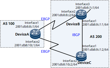
In Figure 1, DeviceA is in AS 100, and DeviceB and DeviceC are in AS 200. EBGP connections are established between DeviceA and DeviceB and between DeviceA and DeviceC.
Service traffic is transmitted over the primary link DeviceA -> DeviceB. The link DeviceA -> DeviceC -> DeviceB serves as the backup link.
BFD is used to detect the BGP peer relationship between DeviceA and DeviceB. If the link between DeviceA and DeviceB fails, BFD can rapidly detect the failure and report it to BGP. This allows service traffic to be quickly switched to the backup link.

Configuration Roadmap
The configuration roadmap is as follows:
Configure basic BGP4+ functions on each router.
Configure the MED attribute on DeviceB and DeviceC to control route selection, allowing traffic to be transmitted over the primary link between DeviceA and DeviceB.
Enable BFD on DeviceA and DeviceB.
Data Preparation
To complete the configuration, you need the following data:
Router IDs and AS numbers of DeviceA, DeviceB, and DeviceC
IPv6 address of the remote end on a BFD session
Minimum interval at which BFD Control packets are received and sent and the local detection multiplier
Procedure
- Configure an IPv6 address for each router. For configuration details, see Configuration Files in this section.
- Configure basic BGP4+ functions, establish EBGP connections between DeviceA and DeviceB and between DeviceA and DeviceC, and establish an IBGP connection between DeviceB and DeviceC.
# Configure DeviceA.
[~DeviceA] bgp 100
[*DeviceA-bgp] router-id 1.1.1.1
[*DeviceA-bgp] peer 2001:db8:8::2 as-number 200
[*DeviceA-bgp] peer 2001:db8:10::2 as-number 200
[*DeviceA-bgp] ipv6-family unicast
[*DeviceA-bgp-af-ipv6] peer 2001:db8:8::2 enable
[*DeviceA-bgp-af-ipv6] peer 2001:db8:10::2 enable
[*DeviceA-bgp-af-ipv6] commit
[~DeviceA-bgp-af-ipv6] quit
[~DeviceA-bgp] quit
# Configure DeviceB.
[~DeviceB] bgp 200
[*DeviceB-bgp] router-id 2.2.2.2
[*DeviceB-bgp] peer 2001:db8:8::1 as-number 100
[*DeviceB-bgp] peer 2001:db8:9::1:2 as-number 200
[*DeviceB-bgp] ipv6-family unicast
[*DeviceB-bgp-af-ipv6] peer 2001:db8:8::1 enable
[*DeviceB-bgp-af-ipv6] peer 2001:db8:9::1:2 enable
[*DeviceB-bgp-af-ipv6] network 2001:db8:7::1 64
[*DeviceB-bgp-af-ipv6] commit
[~DeviceB-bgp-af-ipv6] quit
[~DeviceB-bgp] quit
# Configure DeviceC.
[~Devicec] bgp 200
[*Devicec-bgp] router-id 3.3.3.3
[*Devicec-bgp] peer 2001:db8:10::1 as-number 100
[*Devicec-bgp] peer 2001:db8:9::1:1 as-number 200
[*DeviceC-bgp] ipv6-family unicast
[*DeviceC-bgp-af-ipv6] peer 2001:db8:10::1 enable
[*DeviceC-bgp-af-ipv6] peer 2001:db8:9::1:1 enable
[*DeviceC-bgp-af-ipv6] commit
[~DeviceC-bgp-af-ipv6] quit
[~DeviceC-bgp] quit
# Display information about the BGP peer relationship on DeviceA. The following command output shows that the BGP peer relationship has been established on the device.
<DeviceA> display bgp ipv6 peer BGP local router ID : 1.1.1.1 Local AS number : 100 Total number of peers : 2 Peers in established state : 2 Peer V AS MsgRcvd MsgSent OutQ Up/Down State PrefRcv 2001:db8:8::2 4 200 12 11 0 00:07:26 Established 0 2001:db8:10::2 4 200 12 12 0 00:07:21 Established 0 - Configure BFD to detect the BGP peer relationship between DeviceA and DeviceB.
# Enable BFD on DeviceA and establish a BFD session to detect the link between DeviceA and DeviceB.
[~DeviceA] bfd
[*DeviceA-bfd] quit
[*DeviceA] commit
# Enable BFD on DeviceB and establish a BFD session to detect the link between DeviceB and DeviceA.
[~DeviceB] bfd
[*DeviceB-bfd] quit
[*DeviceB] commit
- Configure the MED attribute.
Configure a route-policy to set the MEDs for the routes that DeviceB and DeviceC send to DeviceA.
# Configure DeviceB.
[~DeviceB] route-policy 10 permit node 10
[*DeviceB-route-policy] apply cost 100
[*DeviceB-route-policy] quit
[*DeviceB] bgp 200
[*DeviceB-bgp] ipv6-family unicast
[*DeviceB-bgp-af-ipv6] peer 2001:db8:8::1 route-policy 10 export
[*DeviceB-bgp-af-ipv6] quit
[*DeviceB-bgp] quit
[*DeviceB] commit
# Configure DeviceC.
[~DeviceC] route-policy 10 permit node 10
[*DeviceC-route-policy] apply cost 150
[*DeviceC-route-policy] quit
[*DeviceC] bgp 200
[*DeviceC-bgp] ipv6-family unicast
[*DeviceC-bgp-af-ipv6] peer 2001:db8:10::1 route-policy 10 export
[*DeviceC-bgp-af-ipv6] quit
[*DeviceC-bgp] quit
[*DeviceC] commit
# Display all BGP routes on DeviceA.
<DeviceA> display bgp ipv6 routing-table
 BGP Local router ID is 1.1.1.1
 Status codes: * - valid, > - best, d - damped, x - best external, a - add path,
               h - history,  i - internal, s - suppressed, S - Stale
               Origin : i - IGP, e - EGP, ? - incomplete
 RPKI validation codes: V - valid, I - invalid, N - not-found

 Total Number of Routes: 2
 *>  Network  : 2001:db8:7::                             PrefixLen : 64
     NextHop  : 2001:db8:8::2                            LocPrf    :
     MED      : 100                                      PrefVal   : 0
     Label    :
     Path/Ogn : 200  i
 *
     NextHop  : 2001:db8:10::2                           LocPrf    :
     MED      : 150                                      PrefVal   : 0
     Label    :
     Path/Ogn : 200  i
The preceding command output shows that the next hop address of the BGP route to 2001:db8:7::1/64 is 2001:db8:8::2 and that traffic is transmitted on the primary link DeviceA→DeviceB.
- Configure BFD, and set the interval at which BFD Control packets are received and sent and the local detection multiplier.
# Enable BFD on DeviceA, set the minimum interval at which BFD Control packets are received and sent to 100 ms, and set the local detection multiplier to 4.
[~DeviceA] bfd
[*DeviceA-bfd] quit
[*DeviceA] bgp 100
[*DeviceA-bgp] peer 2001:db8:8::2 bfd enable
[*DeviceA-bgp] peer 2001:db8:8::2 bfd min-tx-interval 100 min-rx-interval 100 detect-multiplier 4
[*DeviceA-bgp] quit
[*DeviceA] commit
# Enable BFD on DeviceB, set the minimum interval at which BFD Control packets are received and sent to 100 ms, and set the local detection multiplier to 4.
[~DeviceB] bfd
[*DeviceB-bfd] quit
[*DeviceB] bgp 200
[*DeviceB-bgp] peer 2001:db8:8::1 bfd enable
[*DeviceB-bgp] peer 2001:db8:8::1 bfd min-tx-interval 100 min-rx-interval 100 detect-multiplier 4
[*DeviceB-bgp] commit
# Display all BFD sessions established by BGP on DeviceA.
<DeviceA> display bgp ipv6 bfd session all
--------------------------------------------------------------------------------
  Local_Address  : 2001:db8:8::1
  Peer_Address   : 2001:db8:8::2
  Tx-interval(ms): 100         Rx-interval(ms): 100
  Multiplier     : 4           Interface      : GigabitEthernet0/1/0
  Session-State  : Up
  Wtr-interval(m): 0
--------------------------------------------------------------------------------
- Verify the configuration.
# Run the shutdown command on GE 0/1/8 of DeviceB to simulate a fault in the primary link.
[~DeviceB] interface gigabitethernet 0/1/8
[~DeviceB-Gigabitethernet0/1/8] shutdown
# Check the BGP routing table on routerDeviceA.
<DeviceA> display bgp ipv6 routing-table
 Total Number of Routes: 1

 BGP Local router ID is 1.1.1.1
 Status codes: * - valid, > - best, d - damped, x - best external, a - add path,
               h - history,  i - internal, s - suppressed, S - Stale
               Origin : i - IGP, e - EGP, ? - incomplete
 RPKI validation codes: V - valid, I - invalid, N - not-found

 *>  Network  : 2001:db8:7::                             PrefixLen : 64
     NextHop  : 2001:db8:10::2                          LocPrf    :
     MED      : 150                                      PrefVal   : 0
     Label    :
     Path/Ogn : 200  i
The preceding command output shows that the next hop address of the BGP route to 2001:db8:7::1/64 becomes 2001:db8:10::2 and that the backup link DeviceA → DeviceC → DeviceB takes effect after the primary link fails.
Configuration Files
DeviceA configuration file
#
sysname DeviceA
#
bfd
#
interface GigabitEthernet0/1/0
 undo shutdown
 ipv6 enable
 ipv6 address 2001:db8:8::1/64
#
interface GigabitEthernet0/1/8
 undo shutdown
 ipv6 enable
 ipv6 address 2001:db8:10::1/64
#
bgp 100
 router-id 1.1.1.1
 peer 2001:db8:8::2 as-number 200
 peer 2001:db8:8::2 bfd min-tx-interval 100 min-rx-interval 100 detect-multiplier 4
 peer 2001:db8:8::2 bfd enable
 peer 2001:db8:10::2 as-number 200
 #
 ipv4-family unicast
  undo synchronization
 #
 ipv6-family unicast
  undo synchronization
  peer 2001:db8:8::2 enable
  peer 2001:db8:10::2 enable
#
return
DeviceB configuration file
#
sysname DeviceB
#
bfd
#
interface GigabitEthernet0/1/8
 undo shutdown
 ipv6 enable
 ipv6 address 2001:db8:8::2/64
#
interface GigabitEthernet0/1/0
 undo shutdown
 ipv6 enable
 ipv6 address 2001:db8:9::1:1/64
#
interface GigabitEthernet0/1/16
 undo shutdown
 ipv6 enable
 ipv6 address 2001:db8:7::1/64
#
bgp 200
 router-id 2.2.2.2
 peer 2001:db8:8::1 as-number 100
 peer 2001:db8:8::1 bfd min-tx-interval 100 min-rx-interval 100 detect-multiplier 4
 peer 2001:db8:8::1 bfd enable
 peer 2001:db8:9::1:2 as-number 200
 #
 ipv4-family unicast
  undo synchronization
 #
 ipv6-family unicast
  undo synchronization
  network 2001:db8:7:: 64
  peer 2001:db8:8::1 enable
  peer 2001:db8:8::1 route-policy 10 export
  peer 2001:db8:9::1:2 enable
#
route-policy 10 permit node 10
 apply cost 100
#
return
DeviceC configuration file
#
sysname DeviceC
#
interface GigabitEthernet0/1/0
 undo shutdown
 ipv6 enable
 ipv6 address 2001:db8:9::1:2/64
#
interface GigabitEthernet0/1/8
 undo shutdown
 ipv6 enable
 ipv6 address 2001:db8:10::2/64
#
bgp 200
 router-id 3.3.3.3
 peer 2001:db8:9::1:1 as-number 200
 peer 2001:db8:10::1 as-number 100
 #
 ipv4-family unicast
  undo synchronization
 #
 ipv6-family unicast
  undo synchronization
  peer 2001:db8:9::1:1 enable
  peer 2001:db8:10::1 enable
  peer 2001:db8:10::1 route-policy 10 export
#
route-policy 10 permit node 10
 apply cost 150
#
return