Example for Configuring BGP4+ 6PE
6PE enables separated IPv6 networks to communicate with each other using the MPLS tunneling technology.
Networking Requirements
BGP4+ 6PE enables IPv6 networks separated by IPv4/MPLS networks to communicate with each other.
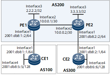
In Figure 1, the IPv6 network where CE1 resides and the IPv6 network where CE2 resides are connected by an IPv4/MPLS network in AS 200. A 6PE peer relationship must be established between PE1 and PE2 so that CE1 and CE2 can communicate with each other across the IPv4/MPLS network. The 6PE peers send IPv6 routes learned from their attached CEs to each other using MP-BGP, and forward IPv6 data over an LDP LSP.

Configuration Roadmap
The configuration roadmap is as follows:
Configure OSPF on PE1 and PE2 to make them learn loopback interface addresses from each other.
Enable MPLS and MPLS LDP on the backbone network so that an LDP LSP can be established between PEs.
Establish a 6PE peer relationship between PE1 and PE2.
- Configure loopback interface addresses on CE1 and CE2 to simulate directly connected subnets.
Configure BGP4+ on PEs and CEs to exchange IPv6 routes.
Data Preparation
To complete the configuration, you need the following data:
Router ID of each device
Number of the AS where each device resides
Procedure
- Configure IPv4 and IPv6 addresses for each interface. For configuration details, see Configuration Files in this section.
- Configure OSPF on PE1 and PE2 so that they learn loopback interface addresses from each other. For details, see Configuration Files in this section.
- Enable MPLS and MPLS LDP on the backbone network so that an LDP LSP can be established between the PEs.
# Configure PE1.
[~PE1] mpls lsr-id 2.2.2.2
[*PE1] mpls
[*PE1-mpls] quit
[*PE1] mpls ldp
[*PE1-mpls-ldp] quit
[*PE1] interface gigabitethernet0/1/8
[*PE1-GigabitEthernet0/1/8] mpls
[*PE1-GigabitEthernet0/1/8] mpls ldp
[*PE1-GigabitEthernet0/1/8] quit
[*PE1] commit
# Configure PE2.
[~PE2] mpls lsr-id 3.3.3.3
[*PE2] mpls
[*PE2-mpls] quit
[*PE2] mpls ldp
[*PE2-mpls-ldp] quit
[*PE2] interface gigabitethernet0/1/8
[*PE2-GigabitEthernet0/1/8] mpls
[*PE2-GigabitEthernet0/1/8] mpls ldp
[*PE2-GigabitEthernet0/1/8] quit
[*PE2] commit
After completing the preceding configurations, run the display mpls ldp session command on each PE. The following command output shows that an LDP session has been established between the PEs.
[~PE1] display mpls ldp session
 LDP Session(s) in Public Network
 Codes: LAM(Label Advertisement Mode), SsnAge Unit(DDDD:HH:MM)
 An asterisk (*) before a session means the session is being deleted.


--------------------------------------------------------------------------
 PeerID             Status      LAM  SsnRole  SsnAge       KASent/Rcv
--------------------------------------------------------------------------
 3.3.3.3:0         Operational DU   Passive  0000:00:35   143/199
--------------------------------------------------------------------------
TOTAL: 1 Session(s) Found.
- Establish a 6PE peer relationship between the PEs.
# Configure PE1.
[~PE1] bgp 200
[*PE1-bgp] peer 3.3.3.3 as-number 200
[*PE1-bgp] peer 3.3.3.3 connect-interface LoopBack0
[*PE1-bgp] ipv6-family unicast
[*PE1-bgp-af-ipv6] import-route direct
[*PE1-bgp-af-ipv6] peer 3.3.3.3 enable
[*PE1-bgp-af-ipv6] peer 3.3.3.3 label-route-capability
[*PE1-bgp-af-ipv6] quit
[*PE1-bgp] quit
[*PE1] commit
# Configure PE2.
[~PE2] bgp 200
[*PE2-bgp] peer 2.2.2.2 as-number 200
[*PE2-bgp] peer 2.2.2.2 connect-interface LoopBack0
[*PE2-bgp] ipv6-family unicast
[*PE2-bgp-af-ipv6] import-route direct
[*PE2-bgp-af-ipv6] peer 2.2.2.2 enable
[*PE2-bgp-af-ipv6] peer 2.2.2.2 label-route-capability
[*PE2-bgp-af-ipv6] commit
[~PE2-bgp-af-ipv6] quit
[~PE2-bgp] quit
[~PE2] commit
# After completing the preceding configurations, run the display bgp ipv6 peer command on each PE. The following command output shows that a BGP peer relationship has been established between the PEs.
[~PE1] display bgp ipv6 peer BGP local router ID : 10.0.0.1 Local AS number : 200 Total number of peers : 2 Peers in established state : 2 Peer V AS MsgRcvd MsgSent OutQ Up/Down State PrefRcv 3.3.3.3 4 200 1248 1342 0 18:06:28 Established 1 - Configure BGP4+ on PEs and CEs to exchange IPv6 routes.
# Configure CE1.
[~CE1] bgp 100
[*CE1-bgp] router-id 5.5.5.5
[*CE1-bgp] peer 2001:db8:1::2 as-number 200
[*CE1-bgp] ipv6-family unicast
[*CE1-bgp-af-ipv6] peer 2001:db8:1::2 enable
[*CE1-bgp-af-ipv6] network 2001:db8:5::5 128
[*CE1-bgp-af-ipv6] commit
[~CE1-bgp-af-ipv6] quit
[~CE1-bgp] quit
# Configure PE1.
[~PE1] bgp 200
[*PE1-bgp] peer 2001:db8:1::1 as-number 100
[*PE1-bgp] ipv6-family unicast
[*PE1-bgp-af-ipv6] peer 2001:db8:1::1 enable
[*PE1-bgp-af-ipv6] commit
[~PE1-bgp-af-ipv6] quit
[~PE1-bgp] quit
# Configure PE2.
[~PE2] bgp 200
[*PE2-bgp] peer 2001:db8:2::1 as-number 300
[*PE2-bgp] ipv6-family unicast
[*PE2-bgp-af-ipv6] peer 2001:db8:2::1 enable
[*PE2-bgp-af-ipv6] commit
[~PE2-bgp-af-ipv6] quit
[~PE2-bgp] quit
# Configure CE2.
[~CE2] bgp 300
[*CE2-bgp] router-id 6.6.6.6
[*CE2-bgp] peer 2001:db8:2::2 as-number 200
[*CE2-bgp] ipv6-family unicast
[*CE2-bgp-af-ipv6] peer 2001:db8:2::2 enable
[*CE2-bgp-af-ipv6] network 2001:db8:6::6 128
[*CE2-bgp-af-ipv6] commit
[~CE2-bgp-af-ipv6] quit
[~CE2-bgp] quit
After completing the preceding configurations, run the display bgp ipv6 peer command on each PE or CE. The following command output shows that the BGP peer relationship has been established between each PE and the corresponding CE.
In the following example, the command output on PE1 is used.
[~PE1] display bgp ipv6 peer BGP local router ID : 10.0.0.1 Local AS number : 100 Total number of peers : 2 Peers in established state : 2 Peer V AS MsgRcvd MsgSent OutQ Up/Down State PrefRcv 3.3.3.3 4 200 59 60 0 00:35:46 Established 1 2001:db8:1::1 4 100 40 45 0 00:06:16 Established 1 - Verify the configuration.
After the preceding configurations are complete, CEs can learn the routes to each other's loopback interface, and ping each other.
In the following example, the command output on CE1 is used.
[~CE1] display ipv6 routing-table
Routing Table : _public_
         Destinations : 8        Routes : 8

 Destination  : ::1                             PrefixLength : 128
 NextHop      : ::1                             Preference   : 0
 Cost         : 0                               Protocol     : Direct
 RelayNextHop : ::                              TunnelID     : 0x0
 Interface    : InLoopBack0                     Flags        : D

 Destination  : ::FFFF:127.0.0.0                PrefixLength : 104
 NextHop      : ::FFFF:127.0.0.0                Preference   : 0
 Cost         : 0                               Protocol     : Direct
 RelayNextHop : ::                              TunnelID     : 0x0
 Interface    : InLoopBack0                     Flags        : D

 Destination  : ::FFFF:127.0.0.0                PrefixLength : 128
 NextHop      : ::1                             Preference   : 0
 Cost         : 0                               Protocol     : Direct
 RelayNextHop : ::                              TunnelID     : 0x0
 Interface    : InLoopBack0                     Flags        : D

 Destination  : 2001:db8:1::                    PrefixLength : 64
 NextHop      : 2001:db8:1::1                   Preference   : 0
 Cost         : 0                               Protocol     : Direct
 RelayNextHop : ::                              TunnelID     : 0x0
 Interface    : GigabitEthernet0/1/0               Flags        : D

 Destination  : 2001:db8:1::1                   PrefixLength : 128
 NextHop      : ::1                             Preference   : 0
 Cost         : 0                               Protocol     : Direct
 RelayNextHop : ::                              TunnelID     : 0x0
 Interface    : GigabitEthernet0/1/0               Flags        : D

 Destination  : 2001:db8:5::5                   PrefixLength : 128
 NextHop      : ::1                             Preference   : 0
 Cost         : 0                               Protocol     : Direct
 RelayNextHop : ::                              TunnelID     : 0x0
 Interface    : LoopBack2                       Flags        : D

 Destination  : 2001:db8:6::6                   PrefixLength : 128
 NextHop      : 2001:db8:1::2                   Preference   : 255
 Cost         : 0                               Protocol     : BGP
 RelayNextHop : 2001:db8:1::2                   TunnelID     : 0x0
 Interface    : GigabitEthernet0/1/0               Flags        : RD

 Destination  : FE80::                          PrefixLength : 10
 NextHop      : ::                              Preference   : 0
 Cost         : 0                               Protocol     : Direct
 RelayNextHop : ::                              TunnelID     : 0x0
 Interface    : NULL0                           Flags        : D
<CE1> ping ipv6 -a 2001:db8:5::5 2001:db8:6::6

  PING 2001:db8:6::6 : 56  data bytes, press CTRL_C to break
    Reply from 2001:db8:6::6
    bytes=56 Sequence=1 hop limit=62 time=8 ms
    Reply from 2001:db8:6::6
    bytes=56 Sequence=2 hop limit=62 time=2 ms
    Reply from 2001:db8:6::6
    bytes=56 Sequence=3 hop limit=62 time=4 ms
    Reply from 2001:db8:6::6
    bytes=56 Sequence=4 hop limit=62 time=3 ms
    Reply from 2001:db8:6::6
    bytes=56 Sequence=5 hop limit=62 time=4 ms
  ---2001:db8:6::6 ping statistics---
    5 packet(s) transmitted
    5 packet(s) received
    0.00% packet loss
    round-trip min/avg/max=2/4/8 ms
After 6PE is configured, the IPv6 network where CE1 resides and the IPv6 network where CE2 resides can communicate through the IPv4/MPLS network.
Configuration Files
CE1 configuration file
#
sysname CE1
#
interface GigabitEthernet0/1/0
 undo shutdown
 ipv6 enable
 ipv6 address 2001:db8:1::1/64
#
interface LoopBack1
 ipv6 enable
 ipv6 address 2001:db8:5::5/128
#
bgp 100
 router-id 5.5.5.5
 peer 2001:db8:1::2 as-number 200
 #
 ipv4-family unicast
  undo synchronization
 #
 ipv6-family unicast
  undo synchronization
  network 2001:db8:5::5 128
  peer 2001:db8:1::2 enable
#
return
PE1 configuration file
#
sysname PE1
#
mpls lsr-id 2.2.2.2
#
mpls
#
mpls ldp
#
interface GigabitEthernet0/1/0
 undo shutdown
 ipv6 enable
 ipv6 address 2001:db8:1::2/64
#
interface GigabitEthernet0/1/8
 undo shutdown
 ip address 10.0.0.1 255.255.255.252
 mpls
 mpls ldp
#
interface LoopBack0
 ip address 2.2.2.2 255.255.255.255
#
bgp 200
 peer 3.3.3.3 as-number 200
 peer 3.3.3.3 connect-interface LoopBack0
 peer 2001:db8:1::1 as-number 100
#
 ipv4-family unicast
  undo synchronization
  peer 3.3.3.3 enable
 #
 ipv6-family unicast
  undo synchronization
  import-route direct
  peer 3.3.3.3 enable
  peer 3.3.3.3 label-route-capability
  peer 2001:db8:1::1 enable
#
ospf 1
 area 0.0.0.0
  network 2.2.2.2 0.0.0.0
  network 10.0.0.0 0.0.0.3
#
return
PE2 configuration file
#
sysname PE2
#
mpls lsr-id 3.3.3.3
#
mpls
#
mpls ldp
#
interface GigabitEthernet0/1/0
 undo shutdown
 ipv6 enable
 ipv6 address 2001:db8:2::2/64
#
interface GigabitEthernet0/1/8
 undo shutdown
 ip address 10.0.0.2 255.255.255.252
 mpls
 mpls ldp
#
interface LoopBack0
 ip address 3.3.3.3 255.255.255.255
#
bgp 200
 peer 2.2.2.2 as-number 200
 peer 2.2.2.2 connect-interface LoopBack0
 peer 2001:db8:2::1 as-number 300
#
 ipv4-family unicast
  undo synchronization
  peer 2.2.2.2 enable
 #
 ipv6-family unicast
  undo synchronization
  import-route direct
  peer 2.2.2.2 enable
  peer 2.2.2.2 label-route-capability
  peer 2001:db8:2::1 enable
#
ospf 1
 area 0.0.0.0
  network 3.3.3.3 0.0.0.0
  network 10.0.0.0 0.0.0.3
#
return
CE2 configuration file
#
sysname CE2
#
interface GigabitEthernet0/1/0
 undo shutdown
 ipv6 enable
 ipv6 address 2001:db8:2::1/64
#
interface LoopBack1
 ipv6 enable
 ipv6 address 2001:db8:6::6/128
#
bgp 300
 router-id 6.6.6.6
 peer 2001:db8:2::2 as-number 200
 #
 ipv4-family unicast
  undo synchronization
 #
 ipv6-family unicast
  undo synchronization
  network 2001:db8:6::6 128
  peer 2001:db8:2::2 enable
#
return