Example for Configuring BFD for BGP
After BFD for BGP is configured, BFD can fast detect the link fault between BGP peers and notify it to BGP so that service traffic can be transmitted along the backup link.
Networking Requirements
Voice and video services have high requirements for network reliability and stability. If a fault occurs on a network, quick service recovery is required (within 50 ms). BFD for BGP can meet this requirement.
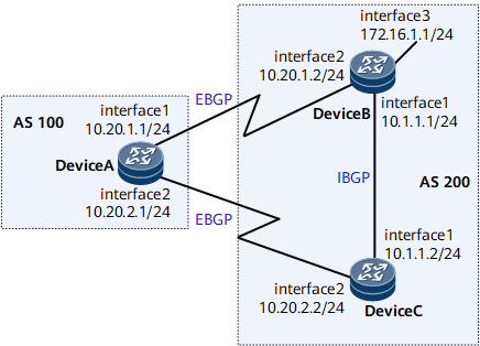
In Figure 1, a primary link and a backup link are deployed on the network to ensure service transmission stability. EBGP peer relationships are established between indirectly connected DeviceA and DeviceB, and between indirectly connected DeviceA and DeviceC. In most cases, traffic is transmitted along the primary link between DeviceA and DeviceB. If the primary link fails, it is required that BGP quickly detect this failure and switch traffic to the backup link (DeviceA -> DeviceC -> DeviceB).
BFD for BGP can be configured to speed up the link switchover. Specifically, BFD is configured to track the BGP peer relationship between DeviceA and DeviceB. If the primary link between DeviceA and DeviceB fails, BFD will quickly detect the fault and notify BGP of the fault so that service traffic is switched to the backup link for transmission.

Interfaces 1 through 3 in this example are GE 0/1/0, GE 0/1/8, GE 0/1/16, respectively.
If two routers establish an EBGP peer relationship over a direct link, BFD for BGP is not required because the ebgp-interface-sensitive command is enabled by default for directly connected EBGP peers.
Precautions
When configuring BFD for BGP, note the following rules:
Before configuring BFD for BGP, enable BFD globally.
When configuring BFD for BGP, ensure that parameters configured on the two ends of a BFD session are consistent.
Configuration Roadmap
The configuration roadmap is as follows:
Configure basic BGP functions on each router.
Configure the MED attribute to control route selection.
Enable BFD on DeviceA and DeviceB
Data Preparation
To complete the configuration, you need the following data:
Router IDs and AS numbers of DeviceA, DeviceB, and DeviceC
Peer IP address to be detected by BFD
Minimum interval at which BFD Control packets are received and sent and the local detection multiplier
Procedure
- Configure an IP address for each interface on the routers. For configuration details, see Configuration Files in this section.
- Configure basic BGP functions, establish EBGP connections between DeviceA and DeviceB, and between DeviceA and DeviceC, and establish an IBGP connection between DeviceB and DeviceC.
# Configure DeviceA.
[~DeviceA] bgp 100
[*DeviceA-bgp] router-id 1.1.1.1
[*DeviceA-bgp] peer 10.20.1.2 as-number 200
[*DeviceA-bgp] peer 10.20.1.2 ebgp-max-hop
[*DeviceA-bgp] peer 10.20.2.2 as-number 200
[*DeviceA-bgp] peer 10.20.2.2 ebgp-max-hop
[*DeviceA-bgp] commit
[~DeviceA-bgp] quit
# Configure DeviceB.
[~DeviceB] bgp 200
[*DeviceB-bgp] router-id 2.2.2.2
[*DeviceB-bgp] peer 10.20.1.1 as-number 100
[*DeviceB-bgp] peer 10.20.1.1 ebgp-max-hop
[*DeviceB-bgp] peer 10.1.1.2 as-number 200
[*DeviceB-bgp] network 172.16.1.0 255.255.255.0
[*DeviceB-bgp] commit
[~DeviceB-bgp] quit
# Configure DeviceC.
[~DeviceC] bgp 200
[*DeviceC-bgp] router-id 3.3.3.3
[*DeviceC-bgp] peer 10.20.2.1 as-number 100
[*DeviceC-bgp] peer 10.20.2.1 ebgp-max-hop
[*DeviceC-bgp] peer 10.1.1.1 as-number 200
[*DeviceC-bgp] commit
[~DeviceC-bgp] quit
# Display peer information on DeviceA. The following command output shows that the BGP peer relationship has been established.
<DeviceA> display bgp peer BGP local router ID : 1.1.1.1 Local AS number : 100 Total number of peers : 2 Peers in established state : 2 Peer V AS MsgRcvd MsgSent OutQ Up/Down State PrefRcv 10.20.1.2 4 200 2 5 0 00:01:25 Established 0 10.20.2.2 4 200 2 4 0 00:00:55 Established 0 - Configure BFD to detect the BGP peer relationship between DeviceA and DeviceB.
# Enable BFD on DeviceA.
[~DeviceA] bfd
[*DeviceA-bfd] quit
[*DeviceA] commit
# Enable BFD on DeviceB.
[~DeviceB] bfd
[*DeviceB-bfd] quit
[*DeviceB] commit
- Configure the MED attribute.
# Configure a route-policy to set the MED value for the routes that DeviceB and DeviceC send to DeviceA.
# Configure DeviceB.
[~DeviceB] route-policy 10 permit node 10
[*DeviceB-route-policy] apply cost 100
[*DeviceB-route-policy] commit
[~DeviceB-route-policy] quit
[~DeviceB] bgp 200
[*DeviceB-bgp] peer 10.20.1.1 route-policy 10 export
[*DeviceB-bgp] commit
# Configure DeviceC.
[~DeviceC] route-policy 10 permit node 10
[*DeviceC-route-policy] apply cost 150
[*DeviceC-route-policy] commit
[~DeviceC-route-policy] quit
[~DeviceC] bgp 200
[*DeviceC-bgp] peer 10.20.2.1 route-policy 10 export
[*DeviceC-bgp] commit
# Display the BGP routing table of DeviceA.
<DeviceA> display bgp routing-table
 BGP Local router ID is 1.1.1.1
 Status codes: * - valid, > - best, d - damped, x - best external, a - add path,
               h - history,  i - internal, s - suppressed, S - Stale
               Origin : i - IGP, e - EGP, ? - incomplete
 RPKI validation codes: V - valid, I - invalid, N - not-found
 Total Number of Routes: 2
      Network            NextHop        MED        LocPrf    PrefVal Path/Ogn
 *>   172.16.1.0/24     10.20.1.2       100                   0      200i
 *                      10.20.2.2       150                   0      200i
According to the preceding BGP routing table, the next hop address of the route to 172.16.1.0/24 is 10.20.1.2, indicating that traffic is transmitted on the primary link (DeviceA→DeviceB).
- Configure BFD, and set the interval at which BFD Control packets are received and sent and the local detection multiplier.
# Enable BFD on DeviceA, set the minimum interval at which BFD Control packets are received and sent to 100 ms, and set the local detection multiplier to 4.
[~DeviceA] bfd
[*DeviceA-bfd] quit
[*DeviceA] bgp 100
[*DeviceA-bgp] peer 10.20.1.2 bfd enable
[*DeviceA-bgp] peer 10.20.1.2 bfd min-tx-interval 100 min-rx-interval 100 detect-multiplier 4
[*DeviceA-bgp] commit
# Enable BFD on DeviceB, set the minimum interval at which BFD Control packets are received and sent to 100 ms, and set the local detection multiplier to 4.
[~DeviceB] bfd
[*DeviceB-bfd] quit
[*DeviceB] bgp 200
[*DeviceB-bgp] peer 10.20.1.1 bfd enable
[*DeviceB-bgp] peer 10.20.1.1 bfd min-tx-interval 100 min-rx-interval 100 detect-multiplier 4
[*DeviceB-bgp] commit
# Check all the BFD sessions established by BGP on DeviceA.
<DeviceA> display bgp bfd session all
--------------------------------------------------------------------------------
  Local_Address      Peer_Address       Interface
  10.20.1.1          10.20.1.2          GigibitEthernet0/1/0
  Tx-interval(ms)    Rx-interval(ms)    Multiplier  Session-State
  100                100                4           Up
  Wtr-interval(m)
  0
--------------------------------------------------------------------------------
- Verify the configuration.
# Run the shutdown command on GE 0/1/8 of DeviceB to simulate a fault on the primary link.
[~DeviceB] interface gigabitethernet 0/1/8
[*DeviceB-GigabitEthernet0/1/8] shutdown
[*DeviceB-GigabitEthernet0/1/8] commit
# Display the BGP routing table of DeviceA.
<DeviceA> display bgp routing-table
 BGP Local router ID is 1.1.1.1
 Status codes: * - valid, > - best, d - damped, x - best external, a - add path,
               h - history,  i - internal, s - suppressed, S - Stale
               Origin : i - IGP, e - EGP, ? - incomplete
 RPKI validation codes: V - valid, I - invalid, N - not-found
 Total Number of Routes: 1
      Network            NextHop        MED        LocPrf    PrefVal Path/Ogn
 *>   172.16.1.0/24      10.20.2.2       150                   0      200i
The command output shows that the backup link DeviceA→DeviceC→DeviceB takes effect after the primary link fails and that the next hop address of the route to 172.16.1.0/24 has become 10.20.2.2.
Configuration Files
DeviceA configuration file
#
sysname DeviceA
#
bfd
#
interface GigabitEthernet0/1/0
 undo shutdown
 ip address 10.20.1.1 255.255.255.0
#
interface GigabitEthernet0/1/8
 undo shutdown
 ip address 10.20.2.1 255.255.255.0
#
bgp 100
 router-id 1.1.1.1
 peer 10.20.1.2 as-number 200
 peer 10.20.1.2 ebgp-max-hop 255
 peer 10.20.1.2 bfd min-tx-interval 100 min-rx-interval 100 detect-multiplier 4
 peer 10.20.1.2 bfd enable
 peer 10.20.2.2 as-number 200
 peer 10.20.2.2 ebgp-max-hop 255
 #
 ipv4-family unicast
  undo synchronization
  peer 10.20.1.2 enable
  peer 10.20.2.2 enable
#
return
DeviceB configuration file
#
sysname DeviceB
#
bfd
#
interface GigabitEthernet0/1/0
 undo shutdown
 ip address 10.1.1.1 255.255.255.0
#
interface GigabitEthernet0/1/8
 undo shutdown
 ip address 10.20.1.2 255.255.255.0
#
interface GigabitEthernet0/1/16
 undo shutdown
 ip address 172.16.1.1 255.255.255.0
#
bgp 200
 router-id 2.2.2.2
 peer 10.1.1.2 as-number 200
 peer 10.20.1.1 as-number 100
 peer 10.20.1.1 ebgp-max-hop 255
 peer 10.20.1.1 bfd min-tx-interval 100 min-rx-interval 100 detect-multiplier 4
 peer 10.20.1.1 bfd enable
 #
 ipv4-family unicast
  undo synchronization
  network 172.16.1.0 255.255.255.0
  peer 10.1.1.2 enable
  peer 10.20.1.1 enable
  peer 10.20.1.1 route-policy 10 export
#
route-policy 10 permit node 10
 apply cost 100
#
return
DeviceC configuration file
#
sysname DeviceC
#
bfd
#
interface GigabitEthernet0/1/0
 undo shutdown
 ip address 10.1.1.2 255.255.255.0
#
interface GigabitEthernet0/1/8
 undo shutdown
 ip address 10.20.2.2 255.255.255.0
#
bgp 200
 router-id 3.3.3.3
 peer 10.1.1.1 as-number 200
 peer 10.20.2.1 as-number 100
 peer 10.20.2.1 ebgp-max-hop 255
 #
 ipv4-family unicast
  undo synchronization
  peer 10.1.1.1 enable
  peer 10.20.2.1 enable
  peer 10.20.2.1 route-policy 10 export
#
route-policy 10 permit node 10
 apply cost 150
#
return