Bit Error Detection
Background
Bit-error-triggered protection switching enables link bit errors to trigger protection switching on network applications, minimizing the impact of bit errors on services. To implement bit-error-triggered protection switching, establish an effective bit error detection mechanism to ensure that network applications promptly detect bit errors.
Related Concepts
Bit error detection involves the following concepts:
Bit error: deviation between a bit that is sent and the bit that is received.
BER: number of bit errors divided by the total number of transferred bits during a certain period. The BER can be considered as an approximate estimate of the probability of a bit error occurring on any particular bit.
LSP BER: calculation result based on the BER of each node on an LSP.
Interface-based Bit Error Detection
A device uses the CRC algorithm to detect bit errors on an inbound interface and calculate the BER. If the BER exceeds the bit error alarm threshold configured on a device's interface, the device determines that bit errors have occurred on the interface's link, and instructs an upper-layer application to perform a service switchover. When the BER of the interface falls below the bit error alarm clear threshold, the device determines that the bit errors have been cleared from the interface, and instructs the upper-layer application to perform a service switchback. To prevent line jitters from frequently triggering service switchovers and switchbacks, set the bit error alarm clear threshold to be one order of magnitude lower than the bit error alarm threshold.
Interfaces support the following types of bit error detection functions:
Trigger-LSP: applies to bit-error-triggered RSVP-TE tunnel, PW, or L3VPN switching.
Trigger-section: applies to bit-error-triggered section switching.
Link-quality: applies to link quality adjustment. This type of detection triggers route cost changes and in turn route reconvergence to prevent bit errors from affecting services.
Advertisement of the Bit Error Status
BFD mode
For dynamic services that use BFD to detect faults, a device uses BFD packets to advertise the bit error status (including the BER). If the BER exceeds the bit error alarm threshold configured on a device's interface, the device determines that bit errors have occurred on the interface's link, and instructs an upper-layer application to perform a service switchover. The device also notifies the BFD module of the bit error status, and then uses BFD packets to advertise the bit error status to the peer device. If bit-error-triggered protection switching also has been deployed on the peer device, the peer device performs protection switching.
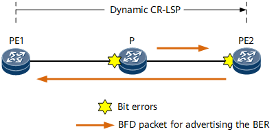
If a transit node or the egress of a dynamic CR-LSP detects bit errors, the transit node or egress must use BFD packets to advertise the BER. On the network shown in Figure 1, a dynamic CR-LSP is deployed from PE1 to PE2. If both the transit node P and egress PE2 detect bit errors:
The P node obtains the local BER and sends PE2 a BFD packet carrying the BER.
PE2 obtains the local BER. After receiving the BER from the P node, PE2 calculates the BER of the CR-LSP based on the BER received and the local BER.
PE2 sends PE1 a BFD packet carrying the BER of the CR-LSP.
After receiving the BER of the CR-LSP, PE1 determines the bit error status based on a specified threshold. If the BER exceeds the threshold, PE1 performs protection switching.
MPLS-TP OAM mode
For static services that use MPLS-TP OAM to detect faults, a device uses MPLS-TP OAM to advertise the bit error status. If the BER reaches the bit error alarm threshold configured on an interface of a device along a static CR-LSP or PW, the device determines that bit errors have occurred on the interface's link, and notifies the MPLS-TP OAM module. The MPLS-TP OAM module uses AIS packets to advertise the bit error status to the egress, and then APS is used to trigger a traffic switchover.
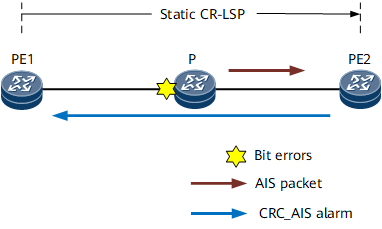
If a transit node detects bit errors on a static CR-LSP or PW, the transit node uses AIS packets to advertise the bit error status to the egress, triggering a traffic switchover on the static CR-LSP or PW. On the network shown in Figure 2, a static CR-LSP is deployed from PE1 to PE2. If the transit node P detects bit errors:
The P node uses AIS packets to notify PE2 of the bit error event.
After receiving the AIS packets, PE2 reports an AIS alarm to trigger local protection switching. PE2 then sends CRC-AIS packets to PE1 and uses the APS protocol to complete protection switching through negotiation with PE1.
After receiving the CRC-AIS packets, PE1 reports a CRC-AIS alarm.