Bit Error Rate-based Selection of an mLDP Tunnel Outbound Interface
Background
In an NG MVPN scenario, multicast data flows must be transmitted on a link that has no or few bit errors because even low bit error rates may cause black screen, erratic display, or frame interruption. If multiple links exist between the upstream and downstream nodes of an mLDP tunnel and some links are logical instead of physical direct links, the upstream node randomly selects an outbound interface by default, and sends packets over the link of the selected interface to the downstream node. Customers require link switching for NG MVPN multicast data flows if the link in use has a high bit error rate. They expect the mLDP upstream node to detect bit error rates of the links and switch to an outbound interface that is connected to a downstream link with few or no bit errors if the link in use is of low quality.
Fundamentals
The upstream and downstream nodes establish an IS-IS neighbor relationship using a logical direct link. BFD-based bit error detection is enabled on the logical interfaces. After the downstream node detects a bit error fault on its inbound interface, the downstream node notifies the interface management module of the fault. The upper-layer service module then takes an action, for example, changing the IGP cost. The downstream node also notifies the BFD module of the bit error status and uses BFD messages to transmit the bit error status and bit error rate to the IS-IS neighbor, that is, the upstream node. If the upstream node is capable of bit error detection based on the IP neighbor type, the BFD module on the upstream node receives the bit error rate. The mLDP tunnel then selects an outbound interface based on the bit error rates of links, implementing association between NG MVPN services and bit error rates. After the bit error fault is rectified, the interface associated with the IS-IS service is restored. For example, the cost of the associated IGP is restored.
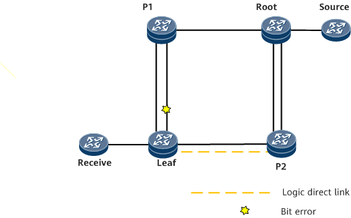
On the network shown in Figure 1, the leaf node and P2 are directly connected using a logical link on the path Leaf-P1-Root-P2. A physical direct link is also available between the leaf node and P2. On the NG MVPN, the leaf node is a downstream node, and P1 and P2 are upstream nodes. Normally, the primary path from the leaf node to the root node is Leaf-P1-Root. If bit errors occur on the interface connecting the leaf node to P1:
The leaf node notifies the local interface management module of the bit error fault, triggering IS-IS to increase the link cost of the interface and switch the IS-IS route to the backup link. The mLDP egress node then selects the backup unicast path Leaf-P2-Root.
The leaf node also uses BFD messages to transmit the bit error status to P2. P2 functions as an mLDP intermediate node and has two links to its downstream node. After P2 receives the bit error rate of the logical direct link, P2 switches the downstream outbound interface to an interface on the physical direct link with no bit errors. mLDP outbound interface switching is then complete.

Currently, bit error rate-based protection switching takes effect only after a neighbor relationship is established, and only mLDP tunnels support bit error rate-based selection of outbound interfaces.
Application Scenarios
In an NG MVPN scenario, multiple links exist between an upstream node and a downstream node, and bit errors need to be detected on logical instead of physical direct links between the two nodes.