Example for Configuring Two-way Frame Delay Measurement in VPLS Networking
This section provides an example showing how to configure two-way frame delay measurement in a VPLS network.
Networking Requirements
As networks rapidly develop and applications diversify, various value-added services, such as Internet Protocol television (IPTV), video conferencing, and Voice over Internet Protocol (VoIP), are more widely used than ever before. Any link connectivity fault or network performance deterioration directly affects service quality on a live network, making performance monitoring on the pipes that transmit these services absolutely essential.
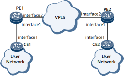
As shown in Figure 1, CFM is configured between each CE and PE and between PEs. To provide high-quality video services, providers hope to monitor the bidirectional delay over mobile bearer links in real time, while monitoring link connectivity. Monitoring the bidirectional delay over mobile bearer links allows the providers to respond quickly to video service quality deterioration.

Configuration Roadmap
The configuration roadmap is as follows:
Configure on-demand two-way frame delay measurement for the PW between the PEs to periodically collect statistics about the delay in frame transmission.
Data Preparation
To complete the configuration, you need the following data:
Configure the name of a VSI and the IP address of the interface of a VPLS.
Configure the names of the MD and MA between PE1 and PE2 and between CE1 and PE1.
Configure the ID of the VLAN to which the interface on the CE belongs during AC-side measurement configuration.
Configure the interval at which DM messages are sent and the number of times when DM messages are sent.
Procedure
- Configure on-demand two-way frame delay measurement for a PW between PEs.
Configure a VPLS connection.
Configure a VPLS connection between PE1 and PE2. The detailed configurations are not provided here. For details, see the chapter "VPLS Configuration" in the HUAWEI NetEngine 8000 F SeriesRouter Configuration Guide - VPN or configuration files in this example.
After completing the configuration, run the display vsi name vsi-name verbose command on each PE to view information about the related VSI and PW.
<PE1> display vsi  name ldp1 verbose
 ***VSI Name               : ldp1
    Administrator VSI      : no
    Isolate Spoken         : disable
    VSI Index              : 1
    PW Signaling           : ldp
    Member Discovery Style : static
    Bridge-domain Mode     : disable
    PW MAC Learn Style     : unqualify
    Encapsulation Type     : vlan
    MTU                    : 1500
    Diffserv Mode          : uniform
    Service Class          : --
    Color                  : --
    DomainId               : 255
    Domain Name            :
    Ignore AcState         : disable
    P2P VSI                : disable
    Create Time            : 0 days, 0 hours, 10 minutes, 10 seconds
    VSI State              : up

    VSI ID                 : 1
   *Peer Router ID         : 1.1.1.1
    primary or secondary   : primary
    ignore-standby-state   : no
    VC Label               : 4187
    Peer Type              : dynamic
    Session                : up
    Tunnel ID              : 0x0000000001004c4b42
    Broadcast Tunnel ID    : --
    Broad BackupTunnel ID  : --
    CKey                   : 1
    NKey                   : 2281701546
    Stp Enable             : 0
    PwIndex                : 1
    Control Word           : enable

    Interface Name         : GigabitEthernet0/1/1.1
    State                  : up
    Access Port            : false
    Last Up Time           : 2013/02/21 08:44:46
    Total Up Time          : 0 days, 0 hours, 0 minutes, 14 seconds

  **PW Information:

   *Peer Ip Address        : 1.1.1.1
    PW State               : up
    Local VC Label         : 4187
    Remote VC Label        : 4187
    Remote Control Word    : enable
    PW Type                : label
    Tunnel ID              : 0x0000000001004c4b42
    Broadcast Tunnel ID    : --
    Broad BackupTunnel ID  : --
    Ckey                   : 1
    Nkey                   : 2281701546
    Main PW Token          : 0x0
    Slave PW Token         : 0x0
    Tnl Type               : ldp
    OutInterface           : LDP LSP
    Backup OutInterface    : --
    Stp Enable             : 0
    PW Last Up Time        : 2013/02/21 08:44:46
    PW Total Up Time       : 0 days, 0 hours, 0 minutes, 14 seconds
Configure basic Ethernet CFM functions and specify the MEP type as inward.
Configure basic Ethernet CFM functions on each PE. Specify the Ethernet CFM protocol in the version of IEEE Standard 802.1ag-2007. Create an MD named md1 and an MA named ma1, and bind the MA to the VSI.
# Configure PE1.
[~PE1] cfm enable
[*PE1] cfm md md1
[*PE1-md-md1] ma ma1
[*PE1-md-md1-ma-ma1] map vsi ldp1
[*PE1-md-md1-ma-ma1] mep mep-id 1 interface gigabitethernet0/1/1.1 inward
[*PE1-md-md1-ma-ma1] mep ccm-send mep-id 1 enable
[*PE1-md-md1-ma-ma1] remote-mep mep-id 2
[*PE1-md-md1-ma-ma1] remote-mep ccm-receive mep-id 2 enable
[*PE1-md-md1-ma-ma1] test-id 1 mep 1 peer-ip 1.1.1.1
[*PE1-md-md1-ma-ma1] quit
[*PE1-md-md1] quit
[*PE1] commit
# Configure PE2.
[~PE2] cfm enable
[*PE2] cfm md md1
[*PE2-md-md1] ma ma1
[*PE2-md-md1-ma-ma1] map vsi ldp1
[*PE2-md-md1-ma-ma1] mep mep-id 2 interface gigabitethernet0/1/1.1 inward
[*PE2-md-md1-ma-ma1] mep ccm-send mep-id 2 enable
[*PE2-md-md1-ma-ma1] remote-mep mep-id 1
[*PE2-md-md1-ma-ma1] remote-mep ccm-receive mep-id 1 enable
[*PE2-md-md1-ma-ma1] test-id 1 mep 2 peer-ip 2.2.2.2
[*PE2-md-md1-ma-ma1] quit
[*PE2-md-md1] quit
[*PE2] commit
Configure the DMM reception function on PE2.
# Configure PE2.
[~PE2-md-md1-ma-ma1] delay-measure two-way receive test-id 1
[*PE1-md-md1-ma-ma1] quit
[*PE1-md-md1] quit
Enable on-demand two-way frame delay measurement for the PW on the VPLS network.
# Configure PE1.
[*PE1-md-md1-ma-ma1] delay-measure two-way send test-id 1 interval 1000 count 20
[*PE1-md-md1-ma-ma1] quit
[*PE1-md-md1] quit
Verify the configuration.
Run the display y1731 statistic-type command on PE1 to view the statistics about the delay in bidirectional frame transmission.
[PE1] display y1731 statistic-type twoway-delay test-id 1
Latest two-way delay statistics of test-id 1:
--------------------------------------------------------------------------------
Index    Delay(usec)    Delay variation(usec)
--------------------------------------------------------------------------------
    1            422                        -
    2            320                      102
    3            467                      147
    4            309                      158
    5            328                       19
    6            316                       12
    7            336                       20
    8            282                       54
    9            421                      139
   10            287                      134
   11            322                       35
   12            446                      124
   13            275                      171
   14            291                       16
   15            341                       50
--------------------------------------------------------------------------------
Average delay(usec) :        344    Average delay variation(usec) :         84
Maximum delay(usec) :        467    Maximum delay variation(usec) :        171
Minimum delay(usec) :        275    Minimum delay variation(usec) :         12
Configuration Files
PE1 configure file
#
 sysname PE1
#
 cfm version standard
 cfm enable
#
 mpls lsr-id 2.2.2.2
 mpls
#
 mpls l2vpn
#
mpls ldp
#
interface GigabitEthernet0/1/1.1
 vlan-type dot1q 2
 l2 binding vsi ldp1
#
interface GigabitEthernet0/1/2
 undo shutdown
 ip address 10.1.1.1 255.255.255.0
 mpls
 mpls ldp
#
interface LoopBack0
 ip address 2.2.2.2 255.255.255.0
#
ospf 1
 area 0.0.0.0
  network 2.2.2.2 0.0.0.0
  network 10.1.1.0 0.0.0.255
#
cfm md md1
 ma ma1
  map vsi ldp1
  mep mep-id 1 interface GigabitEthernet0/1/1.1 inward
  mep ccm-send mep-id 1 enable
  remote-mep mep-id 2
  remote-mep ccm-receive mep-id 2 enable
  test-id 1 mep 1 peer-ip 1.1.1.1
  delay-measure two-way send test-id 1 interval 1000 count 20
#
return
PE2 configuration file
#
 sysname PE2
#
 cfm version standard
 cfm enable
#
 mpls lsr-id 1.1.1.1
 mpls
#
 mpls l2vpn
#
vsi ldp1 static
 pwsignal ldp
  vsi-id 1
  peer 2.2.2.2
#
mpls ldp
#
#
interface GigabitEthernet0/1/1.1
 vlan-type dot1q 2
 l2 binding vsi ldp1
#
interface GigabitEthernet0/1/2
 undo shutdown
 ip address 10.1.1.2 255.255.255.0
 mpls
 mpls ldp
#
interface LoopBack0
 ip address 1.1.1.1 255.255.255.0
#
ospf 1
 area 0.0.0.0
  network 1.1.1.1 0.0.0.0
  network 10.1.1.0 0.0.0.255
#
cfm md md1
 ma ma1
  map vsi ldp1
  mep mep-id 2 interface GigabitEthernet0/1/1.1 inward
  mep ccm-send mep-id 2 enable
  remote-mep mep-id 1
  remote-mep ccm-receive mep-id 1 enable
  test-id 1 mep 2 peer-ip 2.2.2.2
  delay-measure two-way receive test-id 1
#
return