Example for Configuring the AIS Function
The AIS function defined in Y.1731 supports VLL, VPLS, and VLAN scenarios. This section provides an example showing how to configure the AIS function on a VLL network, and briefly describes the AIS application on a VLAN and VPLS network.
Networking Requirements
AIS is used to prohibit a MEP in an MD of a higher level from sending the same alarm as that sent by a MEP in an MD of a lower level to the NMS.
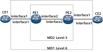
As shown in Figure 1, CE1 is connected to PE1 through sub-interfaces, and CE2 is connected to PE2 through sub-interfaces. A VLL is set up between the PEs, using LDP as the signaling protocol.
VLL AIS is configured on the PEs and alarm suppression is enabled on the CEs. In the scenarios of MD nesting, if a MEP in a low-level MD detects a fault, the MEP sends an alarm to the NMS. After a certain period, a MEP in the MD of a higher level also detects the fault and sends the same alarm to the NMS. In this case, the MEP in the MD of a higher level must be prohibited from sending the same alarm to the NMS.

The VLL between the PEs is used as an example.
Configuration Roadmap
The configuration roadmap is as follows:
Add the PEs to an MD, add each PE and its attached CE to an MD, and ensure that the level of the MD to which the PEs belong is lower than that to which each PE and its attached CE belong.
Configure alarm suppression to suppress MEPs in MDs of different levels from sending the same alarm to the NMS.
Data Preparation
To complete the configuration, you need the following data:
VC ID
- VLAN ID (in VLAN networking)
- VSI name (in VPLS networking)
MD names and MA names on CE1, CE2, PE1, and PE2
Procedure
- Configure a VLL connection.
Configure a VLL connection between PE1 and PE2. The configuration details are not provided here. For details, see the chapter "VLL Configuration" in the Configuration Guide - VPN or configuration files in this configuration example.
By default, the interface type is tagged. The parameter raw can be set in the map mpls l2vc command used to bind the MA to the L2VC only when the parameter raw has been set in the mpls l2vc command used to create a dynamic VLL connection.
In the case of VLAN networking, configure the VLAN between PE1 and PE2. The configuration details are not provided. For details, see the chapter "VLAN Configuration" in the Configuration Guide - LAN Access and MAN Access or configuration files in this configuration example.
In the case of VPLS networking, configure a VPLS connection between PE1 and PE2. The configuration details are not provided here. For details, see the chapter "VPLS Configuration" in the Configuration Guide - VPN or configuration files in this example.
- Configure basic Ethernet CFM functions.
Configure basic Ethernet CFM functions on each PE. Specify the Ethernet CFM protocol in the version of IEEE Standard 802.1ag-2007. Create an MD named md1 and an MA named ma1, and bind the MA to the VLL.
# Configure PE1.
<~HUAWEI> system-view
[*HUAWEI] sysname PE1
[*PE1] cfm version standard
[*PE1] cfm enable
[*PE1] cfm md md1 level 3
[*PE1-md-md1] ma ma1
[*PE1-md-md1-ma-ma1] map mpls l2vc 100 tagged
In VLAN networking, run the following command:
[*PE1-md-md1-ma-ma1] map vlan 2- In VPLS networking, run the following command:
[*PE1-md-md1-ma-ma1] map vsi ldp1
[*PE1-md-md1-ma-ma1] quit
[*PE1-md-md1] quit
# Configure PE2.
<~HUAWEI> system-view
[*HUAWEI] sysname PE2
[*PE2] cfm version standard
[*PE2] cfm enable
[*PE2] cfm md md1 level 3
[*PE2-md-md1] ma ma1
[*PE2-md-md1-ma-ma1] map mpls l2vc 100 tagged
In VLAN networking, run the following command:
[*PE2-md-md1-ma-ma1] map vlan 2- In VPLS networking, run the following command:
[*PE2-md-md1-ma-ma1] map vsi ldp1
[*PE2-md-md1-ma-ma1] quit
[*PE2-md-md1] quit
Configure basic Ethernet CFM functions on each CE. Specify the Ethernet CFM protocol in the version of IEEE Standard 802.1ag-2007. Create an MD named md2 and an MA named ma2.
# Configure CE1.
<~HUAWEI> system-view
[*HUAWEI] sysname CE1
[*CE1] interface GigabitEthernet0/1/1
[*CE1-GigabitEthernet0/1/1] undo shutdown
[*CE1-GigabitEthernet0/1/1] port trunk allow-pass vlan 10
[*CE1-GigabitEthernet0/1/1] quit
[*CE1] cfm version standard
[*CE1] cfm enable
[*CE1] cfm md md2 level 6
[*CE1-md-md2] ma ma2
[*CE1-md-md2-ma-ma2] map vlan 10
[*CE1-md-md2-ma-ma2] quit
[*CE1-md-md2] quit
# Configure CE2.
<~HUAWEI> system-view
[HUAWEI] sysname CE2
[*CE2] interface GigabitEthernet0/1/1
[*CE2-GigabitEthernet0/1/1] undo shutdown
[*CE2-GigabitEthernet0/1/1] port trunk allow-pass vlan 10
[*CE2-GigabitEthernet0/1/1] quit
[*CE2] cfm version standard
[*CE2] cfm enable
[*CE2] cfm md md2 level 6
[*CE2-md-md2] ma ma2
[*CE2-md-md2-ma-ma2] map vlan 10
[*CE2-md-md2-ma-ma2] quit
[*CE2-md-md2] quit
- Set the MEP type as inward on the AC-side interface of each PE (in VLAN networking, set the MEP type on the AC-side interface as outward).
# Configure PE1.
[*PE1] cfm md md1
[*PE1-md-md1] ma ma1
[*PE1-md-md1-ma-ma1] mep mep-id 31 interface gigabitEthernet0/1/1.1 inward
In VPLS networking, the configuration is the same as in the VLL networking. In VLAN networking, run the following commands to set the MEP type as outward:[*PE1-md-md1-ma-ma1] mep mep-id 31 interface gigabitEthernet0/1/1 outward
[*PE1-md-md1-ma-ma1] mep ccm-send enable
[*PE1-md-md1-ma-ma1] remote-mep mep-id 32
[*PE1-md-md1-ma-ma1] remote-mep ccm-receive enable
[*PE1-md-md1-ma-ma1] quit
[*PE1-md-md1] quit
# Configure PE2.
[*PE2] cfm md md1
[*PE2-md-md1] ma ma1
[*PE2-md-md1-ma-ma1] mep mep-id 32 interface gigabitEthernet0/1/1.1 inward
In VPLS networking, the configuration is the same as in the VLL networking. In VLAN networking, run the following commands to set the MEP type as outward:[*PE2-md-md1-ma-ma1] mep mep-id 32 interface gigabitEthernet0/1/1 outward
[*PE2-md-md1-ma-ma1] mep ccm-send enable
[*PE2-md-md1-ma-ma1] remote-mep mep-id 31
[*PE2-md-md1-ma-ma1] remote-mep ccm-receive enable
[*PE2-md-md1-ma-ma1] quit
[*PE2-md-md1] quit
- Set the MEP type as outward on each CE.
# Configure CE1.
[*CE1] cfm md md2
[*CE1-md-md2] ma ma2
[*CE1-md-md2-ma-ma2] mep mep-id 61 interface gigabitEthernet0/1/1 outward
[*CE1-md-md2-ma-ma2] ccm-interval 10000
[*CE1-md-md2-ma-ma2] mep ccm-send enable
[*CE1-md-md2-ma-ma2] remote-mep mep-id 62
[*CE1-md-md2-ma-ma2] remote-mep ccm-receive enable
[*CE1-md-md2-ma-ma2] quit
[*CE1-md-md2] quit
# Configure CE2.
[*CE2] cfm md md2
[*CE2-md-md2] ma ma2
[*CE2-md-md2-ma-ma2] mep mep-id 62 interface gigabitEthernet0/1/1 outward
[*CE2-md-md2-ma-ma2] ccm-interval 10000
[*CE2-md-md2-ma-ma2] mep ccm-send enable
[*CE2-md-md2-ma-ma2] remote-mep mep-id 61
[*CE2-md-md2-ma-ma2] remote-mep ccm-receive enable
[*CE2-md-md2-ma-ma2] quit
[*CE2-md-md2] quit
- Configure the AIS function.
# Configure PE1.
[*PE1] cfm md md1
[*PE1-md-md1] ma ma1
[*PE1-md-md1-ma-ma1] ais enable
[*PE1-md-md1-ma-ma1] ais link-status interface gigabitEthernet0/1/2
[*PE1-md-md1-ma-ma1] ais level 6
[*PE1-md-md1-ma-ma1] ais interval 60
[*PE1-md-md1-ma-ma1] ais vlan vid 10 mep 31
[*PE1-md-md1] quit
[*PE1-md-md1] commit
# Configure PE2.
[*PE2] cfm md md1
[*PE2-md-md1] ma ma1
[*PE2-md-md1-ma-ma1] ais enable
[*PE2-md-md1-ma-ma1] ais link-status interface gigabitEthernet0/1/2
[*PE2-md-md1-ma-ma1] ais level 6
[*PE2-md-md1-ma-ma1] ais interval 60
[*PE2-md-md1-ma-ma1] ais vlan vid 10 mep 32
[*PE2-md-md1-ma-ma1] quit
[*PE2-md-md1] quit
[*PE2-md-md1] commit
- Enable alarm suppression.
# Configure CE1.
[*CE1] cfm md md2
[*CE1-md-md2] ma ma2
[*CE1-md-md2-ma-ma2] ais enable
[*CE1-md-md2-ma-ma2] ais suppress-alarm
[*CE1-md-md2-ma-ma2] quit
[*CE1-md-md2] quit
[*CE1-md-md2] commit
# Configure CE2
[*CE2] cfm md md2
[*CE2-md-md2] ma ma2
[*CE2-md-md2-ma-ma2] ais enable
[*CE2-md-md2-ma-ma2] ais suppress-alarm
[*CE2-md-md2-ma-ma2] quit
[*CE2-md-md2] quit
[*CE2-md-md2] commit
- Verify the configuration.
If a fault occurs in the VLL between PE1 and PE2 after the preceding configuration is complete, run the display cfm ma md md1 ma ma1 command on PE1. The value of the Sending Ais Packet field is displayed as Yes in the command output. Run the display cfm ma md md2 ma ma2 command on CE1. The value of the Suppressing Alarms field is displayed as Yes in the command output.
[~PE1] display cfm ma md md1 ma ma1
The total number of MAs is 1
  MD Name            : md1
  MD Name Format     : string
  Level              : 3
  MIP Create-type    : none
  SenderID TLV-type  : Defer
  MA Name            : ma1
  MA Name Format     : string
  Interval           : 1000
  Priority           : 4
  Vlan ID            : --
  VSI Name           : --   L2VC ID            : 100 tagged   L2VPN Name         : --   CE ID              : --   CE Offset          : --   L2TPV3 Tunnel Name            : --   L2TPV3 Local Connection Name  : --
  MEP Number         : 31
  RMEP Number        : 32
  Suppressing Alarms : No
  Sending Ais Packet : Yes
  Interface TLV      : disabled
[~CE1] display cfm ma md md2 ma ma2
  MD Name            : md2
  MD Name Format     : string
  Level              : 6
  MIP Create-type    : none
  SenderID TLV-type  : Defer
  MA Name            : ma2
  MA Name Format     : string
  Interval           : 10000
  Priority           : 4
  Vlan ID            : 10
 VSI Name           : --   L2VC ID            : 100 tagged   L2VPN Name         : --   CE ID              : --   CE Offset          : --   L2TPV3 Tunnel Name            : --   L2TPV3 Local Connection Name  : --
  MEP Number         : 61
  RMEP Number        : 62
  Suppressing Alarms : Yes
  Sending Ais Packet : NO
  Interface TLV      : disabled
Configuration Files
PE1 configuration file
#
 sysname PE1
#
 cfm version standard
 cfm enable
#
 mpls lsr-id 1.1.1.1
 mpls
#
 mpls l2vpn
#
mpls ldp
#
 mpls ldp remote-peer 3.3.3.3
 remote-ip 3.3.3.3
#
interface GigabitEthernet0/1/1
 undo shutdown
#
interface GigabitEthernet0/1/1.1
 vlan-type dot1q 10
 mpls l2vc 3.3.3.3 100
#
interface GigabitEthernet0/1/2

 undo shutdown
 ip address 10.1.1.1 255.255.255.252
 mpls
 mpls ldp
#
interface LoopBack1
 ip address 1.1.1.1 255.255.255.255
#
ospf 1
 area 0.0.0.0
  network 1.1.1.1 0.0.0.0
  network 10.1.1.0 0.0.0.3
#
 cfm md md1 level 3
  ma ma1
   map mpls l2vc 100 tagged
   mep mep-id 31 interface GigabitEthernet0/1/1.1 inward
   mep ccm-send enable
   remote-mep mep-id 32
   remote-mep ccm-receive enable
   ais enable
   ais link-status interface gigabitEthernet0/1/2
   ais level 6
   ais interval 60
   ais vlan vid 10 mep 31
#
return
P configuration file
#
 sysname P
#
 mpls lsr-id 2.2.2.2
 mpls
#
mpls ldp
#
interface GigabitEthernet0/1/1
 undo shutdown
 ip address 10.2.1.1 255.255.255.252
 mpls
 mpls ldp
#
interface GigabitEthernet0/1/2
 undo shutdown
 ip address 10.1.1.2 255.255.255.252
 mpls
 mpls ldp
#
interface LoopBack1
 ip address 2.2.2.2 255.255.255.255
#
ospf 1
 area 0.0.0.0
  network 2.2.2.2 0.0.0.0
  network 10.1.1.0 0.0.0.3
  network 10.2.1.0 0.0.0.3
#
return
PE2 configuration file
#
 sysname PE2
#
 cfm version standard
 cfm enable
#
 mpls lsr-id 3.3.3.3
 mpls
#
 mpls l2vpn

#
mpls ldp
#
 mpls ldp remote-peer 1.1.1.1
 remote-ip 1.1.1.1
#
interface GigabitEthernet0/1/1
 undo shutdown
#
interface GigabitEthernet0/1/1.1
 vlan-type dot1q 10
 mpls l2vc 1.1.1.1 100
#
interface GigabitEthernet0/1/2
 undo shutdown
 ip address 10.2.1.2 255.255.255.252
 mpls
 mpls ldp
#
interface LoopBack1
 ip address 3.3.3.3 255.255.255.255
#
ospf 1
 area 0.0.0.0
  network 5.5.5.5 0.0.0.0
  network 10.2.1.0 0.0.0.3
#
 cfm md md1 level 3
  ma ma1
   map mpls l2vc 100 tagged
   mep mep-id 32 interface GigabitEthernet0/1/1.1 inward
   mep ccm-send enable
   remote-mep mep-id 31
   remote-mep ccm-receive enable
   ais enable
   ais link-status interface gigabitEthernet0/1/2
   ais level 6
   ais interval 60
   ais vlan vid 10 mep 32
#
return
CE1 configuration file
#
 sysname CE1
#
 cfm version standard
 cfm enable
#
interface GigabitEthernet0/1/1
 undo shutdown
 portswitch
 port trunk allow-pass vlan 10
#
 cfm md md2 level 6
  ma ma2
   map mpls vlan 10
   mep mep-id 61 interface gigabitEthernet0/1/1 outward
   ccm-interval 10000
   mep ccm-send enable
   remote-mep mep-id 62
   remote-mep ccm-receive enable
   ais enable
   ais suppress-alarm
#
return
CE2 configuration file
#
 sysname CE2
#
 cfm version standard
 cfm enable
#
interface GigabitEthernet0/1/1
 undo shutdown
 portswitch
 port trunk allow-pass vlan 10

#
 cfm md md2 level 6
  ma ma2
   map mpls vlan 10
   mep mep-id 62 interface gigabitEthernet0/1/1 outward
   ccm-interval 10000
   mep ccm-send enable
   remote-mep mep-id 61
   remote-mep ccm-receive enable
   ais enable
   ais suppress-alarm
#
return