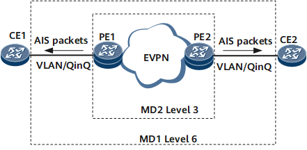
Configuring AIS in EVPN Networking
Configuring AIS prohibits a MEP in an MD of a higher level from sending the same alarm as that sent by a MEP in an MD of a lower level to the NMS.
Context
Procedure
- Perform the following steps on a PE:
Run system-view
The system view is displayed.
Run cfm md md-name
The MD view is displayed.
Run ma ma-name
The MA view is displayed.
Run map evpn vpn-instance evpn-instance-name
Associates the MA with a EVPN instance.
Run ais enable
AIS is enabled for the current MA.
(Optional) Run ais link-status interface { interface-name | interface-type interface-number }
AIS is configured to monitor interfaces in the current MA.
(Optional) Run ais interval interval-value
The interval at which AIS packets are sent is set.

If the range of VLANs to which AIS packets are to be sent is set, setting the interval at which AIS packets are sent to 60s is recommended.
Run ais level level-value
The level of AIS packets to be sent is set.
Run ais vlan { pe-vid pe-vid ce-vid { low-ce-vid [ to hig-ce-vid ] } &<1-10> | vid { low-vid [ to high-vid ] } &<1-10>} mep mep-id
The range of VLANs to which AIS packets are to be sent is set.
Run commit
The configuration is committed.
- Perform the following steps on a CE:
Run system-view
The system view is displayed.
Run cfm md md-name
The MD view is displayed.
Run ma ma-name
The MA view is displayed.
Run map vlan vlan-id
The MA is bound to the current VLAN.
Run ais enable
AIS is enabled for the current MA.
(Optional) Run ais suppress-alarm
Alarm suppression is enabled for the current MA.
In an MD nesting scenario, if alarm suppression is enabled for the MD of a high level, a MEP in this MD does not send alarms that a MEP in an MD of a low level has sent to the NMS after receiving an AIS packet.
Run mep mep-id mep-id alarm ais disable
Disables the alarm reporting function of a specific alarm indication signal (AIS).
Run commit
The configuration is committed.
Checking the Configurations
After completing the configurations, run the display cfm ma command on a PE to check information about MAs.
The command output shows that the Sending Ais Packet field is displayed as Yes.
Run the display cfm ma command on a CE to check information about MAs.
The command output shows that the Suppressing Alarms field is displayed as Yes.