Exampling for Configuring a Hard-Pipe Static SS-PW
This section provides an example for configuring a hard-pipe static SS-PW to carry a leased line service.
Networking Requirements
IP hard pipe is a pipe technology that establishes a static PW over a static bidirectional co-routed LSP to simulate an SDH leased line.
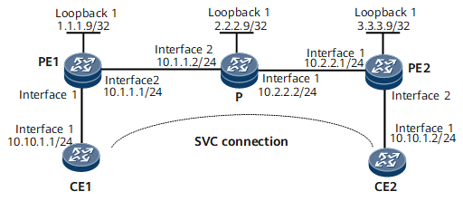
In an IP hard pipe scenario, hard pipe needs to be configured for PWs on the public network side. On the network shown in Figure 1, an SVC needs to be set up between CE1 and CE2. The SVC needs to be created on PEs with specified VC labels.

Configuration Roadmap
The configuration roadmap is as follows:
Configure an IGP on the MPLS backbone network to ensure IP connectivity.
Enable MPLS and MPLS L2VPN.
Create a static L2VC connection between PEs and manually configure VC label information.
Configuring Interface-based Hard Pipe Bandwidth Reservation.
Data Preparation
To complete the configuration, you need the in-label and out-label of the static L2VC connection.
The out-label of PE1 is the same as the in-label of PE2, and the in-label of PE1 is the same as the out-label of PE2.
Procedure
- Assign IP addresses to interfaces on the CEs, PEs, and P as shown in Figure 1.
- Configure an IGP (OSPF in this example) on the MPLS backbone network.
- Configure basic MPLS functions on the MPLS backbone network.
# Configure PE1.
[~PE1] mpls lsr-id 1.1.1.9
[*PE1] mpls
[*PE1-mpls] mpls te
[*PE1-mpls] quit
[*PE1] interface gigabitethernet 0/1/8
[*PE1-GigabitEthernet0/1/8] mpls
[*PE1-GigabitEthernet0/1/8] mpls te
[*PE1-GigabitEthernet0/1/8] quit
[*PE1] commit
# Configure the P.
[~P] mpls lsr-id 2.2.2.9
[*P] mpls
[*P-mpls] mpls te
[*P-mpls] quit
[*P] interface gigabitethernet 0/1/0
[*P-GigabitEthernet1/0/0] mpls
[*P-GigabitEthernet1/0/0] mpls te
[*P-GigabitEthernet1/0/0] quit
[*P] interface gigabitethernet 0/1/8
[*P-GigabitEthernet2/0/0] mpls
[*P-GigabitEthernet2/0/0] mpls te
[*P-GigabitEthernet2/0/0] quit
[*P] commit
# Configure PE2.
[~PE2] mpls lsr-id 3.3.3.9
[*PE2] mpls
[*PE2-mpls] mpls te
[*PE2-mpls] quit
[*PE2] interface gigabitethernet 0/1/0
[*PE2-GigabitEthernet0/1/0] mpls
[*PE2-GigabitEthernet0/1/0] mpls te
[*PE2-GigabitEthernet0/1/0] quit
[*PE2] commit
- Configure MPLS TE tunnel interfaces.
# Configure an MPLS TE tunnel from PE1 to PE2.
[~PE1] interface Tunnel 10
[*PE1-Tunnel10] ip address unnumbered interface loopback 1
[*PE1-Tunnel10] tunnel-protocol mpls te
[*PE1-Tunnel10] destination 3.3.3.9
[*PE1-Tunnel10] mpls te tunnel-id 100
[*PE1-Tunnel10] mpls te signal-protocol cr-static
[*PE1-Tunnel10] mpls te reserved-for-binding
[*PE1-Tunnel10] mpls te bidirectional
[*PE1-Tunnel10] quit
[*PE1] commit
# Configure an MPLS TE tunnel from PE2 to PE1.
[~PE2] interface Tunnel 20
[*PE2-Tunnel20] ip address unnumbered interface loopback 1
[*PE2-Tunnel20] tunnel-protocol mpls te
[*PE2-Tunnel20] destination 1.1.1.9
[*PE2-Tunnel20] mpls te tunnel-id 200
[*PE2-Tunnel20] mpls te signal-protocol cr-static
[*PE2-Tunnel20] mpls te reserved-for-binding
[*PE2-Tunnel20] quit
[*PE2] commit
- Configure the ingress, transit node, and egress for a static bidirectional co-routed LSP.
# Configure PE1 as the ingress.
[~PE1] bidirectional static-cr-lsp ingress Tunnel10
[*PE1-bi-static-ingress-Tunnel10] forward outgoing-interface gigabitethernet0/1/8 nexthop 10.1.1.2 out-label 20
[*PE1-bi-static-ingress-Tunnel10] backward in-label 20
[~PE1-bi-static-ingress-Tunnel10] hard-pipe enable
[*PE1-bi-static-ingress-Tunnel10] quit
[*PE1] commit
# Configure the P as the transit node.
[~P] bidirectional static-cr-lsp transit lsp1
[*P-bi-static-transit-lsp1] forward in-label 20 outgoing-interface gigabitethernet0/1/0 nexthop 10.2.2.1 out-label 40
[*P-bi-static-transit-lsp1] backward in-label 16 outgoing-interface gigabitethernet0/1/8 nexthop 10.1.1.1 out-label 20
[*P-bi-static-transit-lsp1] hard-pipe enable
[*P-bi-static-transit-lsp1] quit
[*P] commit
# Configure PE2 as the egress.
[~PE2] bidirectional static-cr-lsp egress lsp1
[*PE2-bi-static-egress-lsp1] forward in-label 40 lsrid 1.1.1.9 tunnel-id 100
[*PE2-bi-static-egress-lsp1] backward outgoing-interface gigabitethernet0/1/0 nexthop 10.2.2.2 out-label 16
[*PE2-bi-static-egress-lsp1] hard-pipe enable
[*PE2-bi-static-egress-lsp1] quit
[*PE2] commit
- Configure a reverse tunnel attribute on the tunnel interface of PE2 and bind the tunnel interface to the static bidirectional co-routed LSP.
[~PE2] interface Tunnel20
[~PE2-Tunnel20] mpls te passive-tunnel
[*PE2-Tunnel20] mpls te binding bidirectional static-cr-lsp egress lsp1
[*PE2-Tunnel20] quit
[*PE2] commit
- Enable MPLS L2VPN on the PEs and create a static L2VC connection.
# Create a VC on GE0/1/0 that connects PE1 to CE1.
[~PE1] mpls l2vpn
[*PE1-l2vpn] quit
[~PE1] tunnel-policy policy1
[~PE1-policy-policy1] tunnel binding destination 3.3.3.9 te Tunnel 10
[~PE1-policy-policy1] quit
[*PE1] interface gigabitethernet 0/1/0
[*PE1-GigabitEthernet0/1/0] undo shutdown
[*PE1-GigabitEthernet0/1/0] mpls static-l2vc destination 3.3.3.9 transmit-vpn-label 100 receive-vpn-label 200 tunnel-policy policy1
[*PE1-GigabitEthernet0/1/0] mpls l2vpn hard-pipe bandwidth 50 expand-ratio 20
[*PE1-GigabitEthernet0/1/0] quit
[*PE1] commit
# Create a VC on GE0/1/8 that connects PE2 to CE2.
[~PE2] mpls l2vpn
[*PE2-l2vpn] quit
[~PE2] tunnel-policy policy1
[~PE2-policy-policy1] tunnel binding destination 1.1.1.9 te Tunnel 20
[*PE2] interface gigabitethernet 0/1/8
[*PE2-GigabitEthernet0/1/8] undo shutdown
[*PE2-GigabitEthernet0/1/8] mpls static-l2vc destination 1.1.1.9 transmit-vpn-label 200 receive-vpn-label 100 tunnel-policy policy1
[*PE2-GigabitEthernet0/1/0] mpls l2vpn hard-pipe bandwidth 50 expand-ratio 20
[*PE2-GigabitEthernet0/1/8] quit
[*PE2] commit
- Configuring Interface-based Hard Pipe Bandwidth Reservation.
# Configure PE1.
[*PE1] interface gigabitethernet 0/1/8
[*PE1-GigabitEthernet0/1/8] qos hard-pipe share-mode bandwidth 500 outbound
[*PE1] commit
# Configure the P.
[*P] interface gigabitethernet 0/1/0
[*P-GigabitEthernet0/1/0] qos hard-pipe share-mode bandwidth 500 outbound
[*P-GigabitEthernet0/1/0] quit
[*P] interface gigabitethernet 0/1/8
[*P-GigabitEthernet0/1/8] qos hard-pipe share-mode bandwidth 500 outbound
[*P-GigabitEthernet0/1/8] quit
[*P] commit
# Configure PE2.
[*PE2] interface gigabitethernet 0/1/0
[*PE2-GigabitEthernet0/1/0] qos hard-pipe share-mode bandwidth 500 outbound
[*PE2-GigabitEthernet0/1/0] quit
[*PE2] commit
- Verify the configuration.
Run the display mpls static-l2vc hard-pipe command on each PE to check hard-pipe VPWS information. The command output shows that a static L2VC has been set up. The following example uses the command output on PE1.
[~PE1] display mpls static-l2vc hard-pipe
 Total svc connections:  1,  1 up,  0 down

 *Client Interface      : GigabitEthernet0/1/0 is up
  AC Status             : up
  VC State              : up
  VC ID                 : 9
  VC Type               : Ethernet
  Destination           : 3.3.3.9
  Transmit VC Label     : 100
  Receive VC Label      : 200
  Label Status          : 0
  Token Status          : 0
  Control Word          : Disable
  VCCV Capability       : alert ttl lsp-ping bfd
  active state          : inactive
  OAM Protocol          : --
  OAM Status            : --
  OAM Fault Type        : --
  PW APS ID             : --
  PW APS Status         : --
  TTL Value             : 1
  Link State            : up
  Tunnel Policy Name    : policy1
  PW Template Name      : --
  Main or Secondary     : Main
  load balance type     : flow
  Access-port           : false
  VC tunnel/token info  : 1 tunnels/tokens
  NO.0  TNL Type        : te    , TNL ID : 0x000000000300000003
  Create time           : 0 days, 0 hours, 1 minutes, 27 seconds
  UP time               : 0 days, 0 hours, 1 minutes, 27 seconds
  Last change time      : 0 days, 0 hours, 1 minutes, 27 seconds
  VC last up time       : 2015/07/25 16:23:07
  VC total up time      : 0 days, 0 hours, 1 minutes, 27 seconds
  CKey                  : 1
  NKey                  : 3959423113
  Hard-pipe bandwidth   : 50 Kbps
  Hard-pipe expand-ratio: 20 %
Configuration Files
CE1 configuration file
#
 sysname CE1
#
interface GigabitEthernet0/1/0
 undo shutdown
 ip address 10.10.10.1 255.255.255.0
#
return
PE1 configuration file
#
 sysname PE1
#
mpls lsr-id 1.1.1.9
mpls
 mpls te
#
mpls l2vpn
#
tunnel-policy policy1
 tunnel binding destination 3.3.3.9 te Tunnel 10
#
bidirectional static-cr-lsp ingress Tunnel10
 forward outgoing-interface GigabitEthernet0/1/8 nexthop 10.1.1.2 out-label 20
 backward in-label 20
 hard-pipe enable
#
interface GigabitEthernet0/1/0
 undo shutdown
 mpls static-l2vc destination 3.3.3.9 transmit-vpn-label 100 receive-vpn-label 200 tunnel-policy policy1
 mpls l2vpn hard-pipe bandwidth 50 expand-ratio 20
#
interface GigabitEthernet0/1/8
 undo shutdown
 ip address 10.1.1.1 255.255.255.0
 mpls
 mpls te
 qos hard-pipe share-mode bandwidth 500 outbound
#
interface LoopBack1
 ip address 1.1.1.9 255.255.255.255
#
interface Tunnel10
 ip address unnumbered interface loopback 1
 tunnel-protocol mpls te
 destination 3.3.3.9
 mpls te signal-protocol cr-static
 mpls te reserved-for-binding
 mpls te tunnel-id 100
 mpls te bidirectional
#
ospf 1
 area 0.0.0.0
  network 1.1.1.9 0.0.0.0
  network 10.1.1.0 0.0.0.255
#
return
P configuration file
#
 sysname P
#
mpls lsr-id 2.2.2.9
mpls
 mpls te
#
bidirectional static-cr-lsp transit lsp1
 forward in-label 20 outgoing-interface GigabitEthernet0/1/0 nexthop 10.2.2.1 out-label 40
 backward in-label 16 outgoing-interface GigabitEthernet0/1/8 nexthop 10.1.1.1 out-label 20
 hard-pipe enable
#
interface GigabitEthernet0/1/0
 undo shutdown
 ip address 10.2.2.2 255.255.255.0
 mpls
 mpls te
 qos hard-pipe share-mode bandwidth 500 outbound
#
interface GigabitEthernet0/1/8
 undo shutdown
 ip address 10.1.1.2 255.255.255.0
 mpls
 mpls te
 qos hard-pipe share-mode bandwidth 500 outbound
#
interface LoopBack1
 ip address 2.2.2.9 255.255.255.255
#
ospf 1
 area 0.0.0.0
  network 2.2.2.9 0.0.0.0
  network 10.1.1.0 0.0.0.255
  network 10.2.2.0 0.0.0.255
#
return
PE2 configuration file
#
 sysname PE2
#
mpls lsr-id 3.3.3.9
mpls
 mpls te
#
mpls l2vpn
#
tunnel-policy policy1
 tunnel binding destination 1.1.1.9 te Tunnel 20
#
bidirectional static-cr-lsp egress lsp1
 forward in-label 40 lsrid 1.1.1.9 tunnel-id 100
 backward outgoing-interface GigabitEthernet0/1/0 nexthop 10.2.2.2 out-label 16
 hard-pipe enable
#
interface GigabitEthernet0/1/0
 undo shutdown
 ip address 10.2.2.1 255.255.255.0
 mpls
 mpls te
 qos hard-pipe share-mode bandwidth 500 outbound
#
interface GigabitEthernet0/1/8
 undo shutdown
 mpls static-l2vc destination 1.1.1.9 transmit-vpn-label 200 receive-vpn-label 100 tunnel-policy policy1
 mpls l2vpn hard-pipe bandwidth 50 expand-ratio 20
#
interface LoopBack1
 ip address 3.3.3.9 255.255.255.255
#
interface Tunnel20
 ip address unnumbered interface loopback 1
 tunnel-protocol mpls te
 destination 1.1.1.9
 mpls te signal-protocol cr-static
 mpls te reserved-for-binding
 mpls te tunnel-id 200
 mpls te passive-tunnel
 mpls te binding bidirectional static-cr-lsp egress lsp1
#
ospf 1
 area 0.0.0.0
  network 3.3.3.9 0.0.0.0
  network 10.2.2.0 0.0.0.255
#
return
CE2 configuration file
#
 sysname CE2
#
interface GigabitEthernet0/1/0
 undo shutdown
 ip address 10.10.10.2 255.255.255.0
#
return