Exampling for Configuring a Hard-Pipe Static MS-PW
This section provides an example for configuring a hard-pipe static MS-PW to carry a leased line service.
Networking Requirements
IP hard pipe is a pipe technology that establishes a static PW over a static bidirectional co-routed LSP to simulate an SDH leased line.
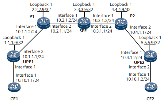
Figure 1 shows an IP hard pipe scenario. CE1 connects to UPE1 and CE2 connects to UPE2. UPE1 and UPE2 need to be connected over a static MS-PW on the MPLS backbone network. A static bidirectional co-routed LSP needs to be configured between UPE1 and UPE2 to carry the static MS-PW.

Configuration Roadmap
The configuration roadmap is as follows:
Enable an IGP on the MPLS backbone network to ensure IP connectivity.
Enable basic MPLS functions on the MPLS backbone network and establish a static bidirectional co-routed LSP.
Set up an MPLS L2VC between UPEs.
Set up a switched PW on the switching node SPE.
Configuring Interface-based Hard Pipe Bandwidth Reservation.
Data Preparation
To complete the configuration, you need the following data:
VC IDs of UPE1 and UPE2 (the two IDs must be different)
LSR IDs of UPE1, UPE2, and the SPE
Peer IP addresses
Encapsulation type of the switched PW
Procedure
- Assign IP addresses to CE interfaces that connect to PEs.
# Configure CE1.
<HUAWEI> system-view
[~HUAWEI] sysname CE1
[*HUAWEI] commit
[~CE1] interface gigabitethernet 0/1/0
[*CE1-GigabitEthernet0/1/0] ip address 10.10.1.1 24
[*CE1-GigabitEthernet0/1/0] undo shutdown
[*CE1-GigabitEthernet0/1/0] quit
[*CE1] commit
# Configure CE2.
<HUAWEI> system-view
[~HUAWEI] sysname CE2
[*HUAWEI] commit
[~CE2] interface gigabitethernet 0/1/0
[*CE2-GigabitEthernet0/1/0] ip address 10.10.1.2 24
[*CE2-GigabitEthernet0/1/0] undo shutdown
[*CE2-GigabitEthernet0/1/0] quit
[*CE2] commit
- Configure an IGP on the MPLS backbone network.
Configure an IGP on the MPLS backbone. In this example, OSPF is used.
Assign IP addresses to the interfaces on UPEs, Ps, and the SPE. Ensure that the 32-bit loopback addresses of UPE1, UPE2, and the SPE are advertised after OSPF is enabled.
# Configure UPE1.
[~UPE1] interface loopback 1
[*UPE1-LoopBack1] ip address 1.1.1.9 32
[*UPE1-LoopBack1] quit
[*UPE1] interface gigabitethernet 0/1/8
[*UPE1-GigabitEthernet0/1/8] ip address 10.1.1.1 24
[*UPE1-GigabitEthernet0/1/8] undo shutdown
[*UPE1-GigabitEthernet0/1/8] quit
[*UPE1] ospf 1
[*UPE1-ospf-1] area 0.0.0.0
[*UPE1-ospf-1-area-0.0.0.0] network 10.1.1.0 0.0.0.255
[*UPE1-ospf-1-area-0.0.0.0] network 1.1.1.9 0.0.0.0
[*UPE1-ospf-1-area-0.0.0.0] quit
[*UPE1-ospf-1] quit
[*UPE1] commit
# Configure P1.
[~P1] interface loopback 1
[*P1-LoopBack1] ip address 2.2.2.9 32
[*P1-LoopBack1] quit
[*P1] interface gigabitethernet 0/1/0
[*P1-GigabitEthernet0/1/0] ip address 10.1.1.2 24
[*P1-GigabitEthernet0/1/0] undo shutdown
[*P1-GigabitEthernet0/1/0] quit
[*P1] interface gigabitethernet 0/1/8
[*P1-GigabitEthernet0/1/8] ip address 10.2.1.1 24
[*P1-GigabitEthernet0/1/8] undo shutdown
[*P1-GigabitEthernet0/1/8] quit
[*P1] ospf 1
[*P1-ospf-1] area 0.0.0.0
[*P1-ospf-1-area-0.0.0.0] network 10.1.1.0 0.0.0.255
[*P1-ospf-1-area-0.0.0.0] network 10.2.1.0 0.0.0.255
[*P1-ospf-1-area-0.0.0.0] network 2.2.2.9 0.0.0.0
[*P1-ospf-1-area-0.0.0.0] quit
[*P1-ospf-1] quit
[*P1] commit
# Configure the SPE.
[~SPE] interface loopback 1
[*SPE-LoopBack1] ip address 3.3.3.9 32
[*SPE-LoopBack1] quit
[*SPE] interface gigabitethernet 0/1/0
[*SPE-GigabitEthernet0/1/0] ip address 10.2.1.2 24
[*SPE-GigabitEthernet0/1/0] undo shutdown
[*SPE-GigabitEthernet0/1/0] quit
[*SPE] interface gigabitethernet 0/1/8
[*SPE-GigabitEthernet0/1/8] ip address 10.3.1.1 24
[*SPE-GigabitEthernet0/1/8] undo shutdown
[*SPE-GigabitEthernet0/1/8] quit
[*SPE] ospf 1
[*SPE-ospf-1] area 0.0.0.0
[*SPE-ospf-1-area-0.0.0.0] network 10.2.1.0 0.0.0.255
[*SPE-ospf-1-area-0.0.0.0] network 10.3.1.0 0.0.0.255
[*SPE-ospf-1-area-0.0.0.0] network 3.3.3.9 0.0.0.0
[*SPE-ospf-1-area-0.0.0.0] quit
[*SPE-ospf-1] quit
[*SPE] commit
# Configure P2.
[~P2] interface loopback 1
[*P2-LoopBack1] ip address 4.4.4.9 32
[*P2-LoopBack1] quit
[*P2] interface gigabitethernet 0/1/0
[*P2-GigabitEthernet0/1/0] ip address 10.3.1.2 24
[*P2-GigabitEthernet0/1/0] undo shutdown
[*P2-GigabitEthernet0/1/0] quit
[*P2] interface gigabitethernet 0/1/8
[*P2-GigabitEthernet0/1/8] ip address 10.4.1.1 24
[*P2-GigabitEthernet0/1/8] undo shutdown
[*P2-GigabitEthernet0/1/8] quit
[*P2] ospf 1
[*P2-ospf-1] area 0.0.0.0
[*P2-ospf-1-area-0.0.0.0] network 10.3.1.0 0.0.0.255
[*P2-ospf-1-area-0.0.0.0] network 10.4.1.0 0.0.0.255
[*P2-ospf-1-area-0.0.0.0] network 4.4.4.9 0.0.0.0
[*P2-ospf-1-area-0.0.0.0] quit
[*P2-ospf-1] quit
[*P2] commit
# Configure UPE2.
[~UPE2] interface loopback 1
[*UPE2-LoopBack1] ip address 5.5.5.9 32
[*UPE2-LoopBack1] quit
[*UPE2] interface gigabitethernet 0/1/0
[*UPE2-GigabitEthernet0/1/0] ip address 10.4.1.2 24
[*UPE2-GigabitEthernet0/1/0] undo shutdown
[*UPE2-GigabitEthernet0/1/0] quit
[*UPE2] ospf 1
[*UPE2-ospf-1] area 0.0.0.0
[*UPE2-ospf-1-area-0.0.0.0] network 10.4.1.0 0.0.0.255
[*UPE2-ospf-1-area-0.0.0.0] network 5.5.5.9 0.0.0.0
[*UPE2-ospf-1-area-0.0.0.0] quit
[*UPE2-ospf-1] quit
[*UPE2] commit
- Configure basic MPLS functions on the MPLS backbone network.
# Configure UPE1.
[~UPE1] mpls lsr-id 1.1.1.9
[*UPE1] mpls
[*UPE1-mpls] mpls te
[*UPE1-mpls] quit
[*UPE1] interface gigabitethernet 0/1/8
[*UPE1-GigabitEthernet0/1/8] undo shutdown
[*UPE1-GigabitEthernet0/1/8] mpls
[*UPE1-GigabitEthernet0/1/8] mpls te
[*UPE1-GigabitEthernet0/1/8] quit
[*UPE1] commit
# Configure P1.
[~P1] mpls lsr-id 2.2.2.9
[*P1] mpls
[*P1-mpls] mpls te
[*P1-mpls] quit
[*P1] interface gigabitethernet 0/1/0
[*P1-GigabitEthernet0/1/0] undo shutdown
[*P1-GigabitEthernet0/1/0] mpls
[*P1-GigabitEthernet0/1/0] mpls te
[*P1-GigabitEthernet0/1/0] quit
[*P1] interface gigabitethernet 0/1/8
[*P1-GigabitEthernet0/1/8] undo shutdown
[*P1-GigabitEthernet0/1/8] mpls
[*P1-GigabitEthernet0/1/8] mpls te
[*P1-GigabitEthernet0/1/8] quit
[*P1] commit
# Configure the SPE.
[~SPE] mpls lsr-id 3.3.3.9
[*SPE] mpls
[*SPE-mpls] mpls te
[*SPE-mpls] quit
[*SPE] interface gigabitethernet 0/1/0
[*SPE-GigabitEthernet0/1/0] undo shutdown
[*SPE-GigabitEthernet0/1/0] mpls
[*SPE-GigabitEthernet0/1/0] mpls te
[*SPE-GigabitEthernet0/1/0] quit
[*SPE] interface gigabitethernet 0/1/8
[*SPE-GigabitEthernet0/1/8] undo shutdown
[*SPE-GigabitEthernet0/1/8] mpls
[*SPE-GigabitEthernet0/1/8] mpls te
[*SPE-GigabitEthernet0/1/8] quit
[*SPE] commit
# Configure P2.
[~P2] mpls lsr-id 4.4.4.9
[*P2] mpls
[*P2-mpls] mpls te
[*P2-mpls] quit
[*P2] interface gigabitethernet 0/1/0
[*P2-GigabitEthernet0/1/0] undo shutdown
[*P2-GigabitEthernet0/1/0] mpls
[*P2-GigabitEthernet0/1/0] mpls te
[*P2-GigabitEthernet0/1/0] quit
[*P2] interface gigabitethernet 0/1/8
[*P2-GigabitEthernet0/1/8] undo shutdown
[*P2-GigabitEthernet0/1/8] mpls
[*P2-GigabitEthernet0/1/8] mpls te
[*P2-GigabitEthernet0/1/8] quit
[*P2] commit
# Configure UPE2.
[~UPE2] mpls lsr-id 5.5.5.9
[*UPE2] mpls
[*UPE2-mpls] mpls te
[*UPE2-mpls] quit
[*UPE2] interface gigabitethernet 0/1/0
[*UPE2-GigabitEthernet0/1/0] undo shutdown
[*UPE2-GigabitEthernet0/1/0] mpls
[*UPE2-GigabitEthernet0/1/0] mpls te
[*UPE2-GigabitEthernet0/1/0] quit
[*UPE2] commit
- Configure MPLS TE tunnel interfaces.
# Configure an MPLS TE tunnel from UPE1 to the SPE.
[~UPE1] interface Tunnel 10
[*UPE1-Tunnel10] ip address unnumbered interface loopback 1
[*UPE1-Tunnel10] tunnel-protocol mpls te
[*UPE1-Tunnel10] destination 3.3.3.9
[*UPE1-Tunnel10] mpls te tunnel-id 100
[*UPE1-Tunnel10] mpls te signal-protocol cr-static
[*UPE1-Tunnel10] mpls te reserved-for-binding
[*UPE1-Tunnel10] mpls te bidirectional
[*UPE1-Tunnel10] quit
[*UPE1] commit
# Configure an MPLS TE tunnel from the SPE to UPE1 and UPE2.
[~SPE] interface Tunnel 10
[*SPE-Tunnel10] ip address unnumbered interface loopback 1
[*SPE-Tunnel10] tunnel-protocol mpls te
[*SPE-Tunnel10] destination 1.1.1.9
[*SPE-Tunnel10] mpls te tunnel-id 100
[*SPE-Tunnel10] mpls te signal-protocol cr-static
[*SPE-Tunnel10] mpls te reserved-for-binding
[*SPE-Tunnel10] mpls te bidirectional
[*SPE-Tunnel10] quit
[~SPE] interface Tunnel 20
[*SPE-Tunnel20] ip address unnumbered interface loopback 1
[*SPE-Tunnel20] tunnel-protocol mpls te
[*SPE-Tunnel20] destination 5.5.5.9
[*SPE-Tunnel20] mpls te tunnel-id 200
[*SPE-Tunnel20] mpls te signal-protocol cr-static
[*SPE-Tunnel20] mpls te reserved-for-binding
[*SPE-Tunnel20] quit
[*SPE] commit
# Configure an MPLS TE tunnel from UPE2 to the SPE.
[~UPE2] interface Tunnel 20
[*UPE2-Tunnel20] ip address unnumbered interface loopback 1
[*UPE2-Tunnel20] tunnel-protocol mpls te
[*UPE2-Tunnel20] destination 3.3.3.9
[*UPE2-Tunnel20] mpls te tunnel-id 200
[*UPE2-Tunnel20] mpls te signal-protocol cr-static
[*UPE2-Tunnel20] mpls te reserved-for-binding
[*UPE2-Tunnel20] quit
[*UPE2] commit
- Configure the ingress, transit node, and egress for a static bidirectional co-routed LSP.
# Configure UPE1 as the ingress for Tunnel 10 from UPE1 to the SPE.
[~UPE1] bidirectional static-cr-lsp ingress Tunnel 10
[*UPE1-bi-static-ingress-Tunnel10] forward outgoing-interface gigabitethernet0/1/8 nexthop 10.1.1.2 out-label 20
[*UPE1-bi-static-ingress-Tunnel10] backward in-label 20
[*UPE1-bi-static-ingress-Tunnel10] hard-pipe enable
[*UPE1-bi-static-ingress-Tunnel10] quit
[*UPE1] commit
# Configure P1 as the transit node for Tunnel 10 from UPE1 to the SPE.
[~P1]bidirectional static-cr-lsp transit lsp1
[*P1-bi-static-transit-lsp1] forward in-label 20 outgoing-interface gigabitethernet 0/1/8 nexthop 10.2.1.2 out-label 40
[*P1-bi-static-transit-lsp1] backward in-label 16 outgoing-interface gigabitethernet 0/1/0 nexthop 10.1.1.1 out-label 20
[*P1-bi-static-transit-lsp1] hard-pipe enable
[*P1-bi-static-transit-lsp1] quit
[*P1] commit
# Configure the SPE as the egress for Tunnel 10 from UPE1 to the SPE and ingress for Tunnel 20 from the SPE to UPE2.
[~SPE] bidirectional static-cr-lsp egress lsp1
[*SPE-bi-static-egress-lsp1] forward in-label 40 lsrid 1.1.1.9 tunnel-id 100
[*SPE-bi-static-egress-lsp1] backward outgoing-interface gigabitethernet 0/1/0 nexthop 10.2.1.1 out-label 16
[*SPE-bi-static-egress-lsp1] hard-pipe enable
[~SPE-bi-static-egress-lsp1] quit
[~SPE] bidirectional static-cr-lsp ingress lsp2
[*SPE-bi-static-egress-lsp2] forward outgoing-interface gigabitethernet 0/1/8 nexthop 10.3.1.2 out-label 60
[*SPE-bi-static-egress-lsp2] backward in-label 60
[*SPE-bi-static-egress-lsp2] hard-pipe enable
[*SPE-bi-static-egress-lsp2] quit
[*SPE] commit
# Configure P2 as the transit node for Tunnel 20 from UPE2 to the SPE.
[~P2]bidirectional static-cr-lsp transit lsp2
[*P2-bi-static-transit-lsp1] forward in-label 60 outgoing-interface gigabitethernet 0/1/8 nexthop 10.4.1.2 out-label 80
[*P2-bi-static-transit-lsp1] backward in-label 50 outgoing-interface gigabitethernet 0/1/0 nexthop 10.3.1.1 out-label 20
[*P2-bi-static-transit-lsp1] hard-pipe enable
[*P2-bi-static-transit-lsp1] quit
[*P2] commit
# Configure UPE2 as the egress for Tunnel 10 from the SPE to UPE2.
[~UPE2] bidirectional static-cr-lsp egress lsp2
[*UPE2-bi-static-egress-lsp2] forward in-label 60 lsrid 3.3.3.9 tunnel-id 200
[*UPE2-bi-static-egress-lsp2] backward outgoing-interface gigabitethernet 0/1/0 nexthop 10.4.1.1 out-label 50
[*UPE2-bi-static-egress-lsp2] hard-pipe enable
[*UPE2-bi-static-egress-lsp2] quit
[*UPE2] commit
- Configure a reverse tunnel attribute on the tunnel interface of UPE2 and the SPE and bind each tunnel interface to the static bidirectional co-routed LSP.
# Configure the SPE.
[~SPE] interface Tunnel20
[~SPE-Tunnel20] mpls te passive-tunnel
[*SPE-Tunnel20] mpls te binding bidirectional static-cr-lsp egress lsp1
[*SPE-Tunnel20] quit
[*SPE] commit
# Configure UPE2.
[~UPE2] interface Tunnel20
[~UPE2-Tunnel20] mpls te passive-tunnel
[*UPE2-Tunnel20] mpls te binding bidirectional static-cr-lsp egress lsp2
[*UPE2-Tunnel20] quit
[*UPE2] commit
- Create VCs.
Enable MPLS L2VPN on UPE1, UPE2, and the SPE, configure a static L2VC on each UPE, and configure a static switched PW on the SPE.
# Configure UPE1.
[~UPE1] mpls l2vpn
[*UPE1-l2vpn] quit
[*UPE1] tunnel-policy policy1
[*UPE1-tunnel-policy-policy1] tunnel binding destination 3.3.3.9 te Tunnel 10
[*UPE1] interface gigabitethernet 0/1/0
[*UPE1-GigabitEthernet0/1/0] undo shutdown
[*UPE1-GigabitEthernet0/1/0] mpls static-l2vc destination 3.3.3.9 transmit-vpn-label 18 receive-vpn-label 18 tunnel-policy policy1
[*UPE1-GigabitEthernet0/1/0] mpls l2vpn hard-pipe bandwidth 50 expand-ratio 20
[*UPE1-GigabitEthernet0/1/0] quit
[*UPE1] commit
# Configure the SPE.
[~SPE] mpls l2vpn
[*SPE-l2vpn] quit
[*SPE] tunnel-policy policy1
[*SPE-tunnel-policy-policy1] tunnel binding destination 1.1.1.9 te Tunnel 20
[*SPE-tunnel-policy-policy1] tunnel binding destination 5.5.5.9 te Tunnel 10
[*SPE-tunnel-policy-policy1] quit
[*SPE] mpls switch-l2vc 1.1.1.9 100 trans 18 recv 18 tunnel-policy policy1 between 5.5.5.9 200 trans 19 recv 19 tunnel-policy policy1 encapsulation ethernet
[*SPE] mpls switch-l2vc 1.1.1.9 100 encapsulation ethernet hard-pipe bandwidth 60 bandwidth 20
[*SPE] mpls switch-l2vc 5.5.5.9 200 encapsulation ethernet hard-pipe bandwidth 60 bandwidth 20
[*SPE] commit
# Configure UPE2.
[~UPE2] mpls l2vpn
[*UPE2-l2vpn] quit
[*UPE2] tunnel-policy policy1
[*UPE2-tunnel-policy-policy1] tunnel binding destination 3.3.3.9 te Tunnel 20
[*UPE2] interface gigabitethernet 0/1/8
[*UPE2-GigabitEthernet0/1/8] undo shutdown
[*UPE2-GigabitEthernet0/1/8] mpls static-l2vc destination 3.3.3.9 transmit-vpn-label 19 receive-vpn-label 19 tunnel-policy policy1
[*UPE2-GigabitEthernet0/1/8] mpls l2vpn hard-pipe bandwidth 50 expand-ratio 20
[*UPE2-GigabitEthernet0/1/8] quit
[*UPE2] commit
- Configuring Interface-based Hard Pipe Bandwidth Reservation.
# ConfigureUPE1.
[*UPE1] interface gigabitethernet 0/1/8
[*UPE1-GigabitEthernet0/1/8] qos hard-pipe share-mode bandwidth 500 outbound
[*UPE1] commit
# ConfigureP1.
[*P1] interface gigabitethernet 0/1/0
[*P1-GigabitEthernet0/1/0] qos hard-pipe share-mode bandwidth 500 outbound
[*P1-GigabitEthernet0/1/0] quit
[*P1] interface gigabitethernet 0/1/8
[*P1-GigabitEthernet0/1/8] qos hard-pipe share-mode bandwidth 500 outbound
[*P1-GigabitEthernet0/1/8] quit
[*P1] commit
# ConfigureSPE.
[*SPE] interface gigabitethernet 0/1/0
[*SPE-GigabitEthernet0/1/0] qos hard-pipe share-mode bandwidth 500 outbound
[*SPE-GigabitEthernet0/1/0] quit
[*SPE] interface gigabitethernet 0/1/8
[*SPE-GigabitEthernet0/1/8] qos hard-pipe share-mode bandwidth 500 outbound
[*SPE-GigabitEthernet0/1/8] quit
[*SPE] commit
# ConfigureP2.
[*P2] interface gigabitethernet 0/1/0
[*P2-GigabitEthernet0/1/0] qos hard-pipe share-mode bandwidth 500 outbound
[*P2-GigabitEthernet0/1/0] quit
[*P2] interface gigabitethernet 0/1/8
[*P2-GigabitEthernet0/1/8] qos hard-pipe share-mode bandwidth 500 outbound
[*P2-GigabitEthernet0/1/8] quit
[*P2] commit
# ConfigureUPE2.
[*UPE2] interface gigabitethernet 0/1/0
[*UPE2-GigabitEthernet0/1/0] qos hard-pipe share-mode bandwidth 500 outbound
[*UPE2-GigabitEthernet0/1/0] quit
[*UPE2] commit
- Verify the configuration.
Check PWE3 connection information.
Check static MS-PW information on the SPE.
[~SPE] display mpls switch-l2vc hard-pipe
 Total Switch VC : 1, 1 up, 0 down

*Switch-l2vc type             : SVC<---->SVC
 Peer IP Address              : 1.1.1.9, 5.5.5.9
 VC ID                        : 100, 200
 VC Type                      : Ethernet
 VC State                     : up
 In/Out Label                 : 18/18, 19/19
 InLabel Status               : 0 , 0
 Control Word                 : Disable, Disable
 VCCV Capability              : alert ttl lsp-ping bfd , alert ttl lsp-ping bfd
 Hard-pipe bandwidth          : 60 Kbps, 60 Kbps
 Hard-pipe expand-ratio       : 20 %, 20 %

 Switch-l2vc tunnel info      :
                                1 tunnels for peer 1.1.1.9
                                NO.0  TNL Type : te    , TNL ID : 0x000000000300000003
                                1 tunnels for peer 5.5.5.9
                                NO.0  TNL Type : te    , TNL ID : 0x000000000300000005
 CKey                         : 1, 2
 NKey                         : 1040187529, 1040187530
 Tunnel policy                : policy1, policy1
 Create time                  : 0 days, 0 hours, 9 minutes, 30 seconds
 UP time                      : 0 days, 0 hours, 9 minutes, 30 seconds
 Last change time             : 0 days, 0 hours, 9 minutes, 30 seconds
 VC last up time              : 2015/07/25 15:34:26
 VC total up time             : 0 days, 0 hours, 9 minutes, 30 seconds
Check whether CE1 and CE2 can communicate.
CE1 and CE2 can ping each other.
[~CE1] ping 10.10.1.2
  PING 10.10.1.2: 56  data bytes, press CTRL_C to break
    Reply from 10.10.1.2: bytes=56 Sequence=1 ttl=255 time=180 ms
    Reply from 10.10.1.2: bytes=56 Sequence=2 ttl=255 time=120 ms
    Reply from 10.10.1.2: bytes=56 Sequence=3 ttl=255 time=160 ms
    Reply from 10.10.1.2: bytes=56 Sequence=4 ttl=255 time=160 ms
    Reply from 10.10.1.2: bytes=56 Sequence=5 ttl=255 time=130 ms
  --- 10.10.1.2 ping statistics ---
    5 packet(s) transmitted
    5 packet(s) received
    0.00% packet loss
    round-trip min/avg/max = 120/150/180 ms
The following example shows information about the path between CE1 and CE2.
[~CE1] tracert 10.10.1.2
traceroute to 10.10.1.2 (10.10.1.2), 30 hops max,press CTRL_C to break
traceroute to 10.10.1.2 (10.10.1.2), max hops: 30, packet length: 40, press CTRL_C to break
 1 10.10.1.2 250 ms  220 ms  130 ms
Configuration Files
CE1 configuration file
# sysname CE1
#
interface GigabitEthernet0/1/0
 undo shutdown
 ip address 10.10.1.1 255.255.255.0
#
return
UPE1 configuration file
#
 sysname UPE1
#
mpls lsr-id 1.1.1.9
mpls
 mpls te
#
mpls l2vpn
#
 bidirectional static-cr-lsp ingress Tunnel 10
 forward outgoing-interface GigabitEthernet0/1/8 nexthop 10.1.1.2 out-label 20
 backward in-label 20
 hard-pipe enable
#
tunnel-policy policy1
 tunnel binding destination 3.3.3.9 te Tunnel 10
#
interface GigabitEthernet0/1/0
 undo shutdown
 mpls static-l2vc destination 3.3.3.9 transmit-vpn-label 18 receive-vpn-label 18 tunnel-policy policy1
 mpls l2vpn hard-pipe bandwidth 50 expand-ratio 20
#
interface GigabitEthernet0/1/8
 undo shutdown
 ip address 10.1.1.1 255.255.255.0
#
mpls
 mpls te
 qos hard-pipe share-mode bandwidth 500 outbound
#
interface LoopBack1
 ip address 1.1.1.9 255.255.255.255
#
interface Tunnel10
 ip address unnumbered interface LoopBack1
 tunnel-protocol mpls te
 destination 3.3.3.9
 mpls te signal-protocol cr-static
 mpls te reserved-for-binding
 mpls te tunnel-id 100
 mpls te bidirectional
#
ospf 1
 area 0.0.0.0
  network 10.1.1.0 0.0.0.255
  network 1.1.1.9 0.0.0.0
#
return
P1 configuration file
#
 sysname P1
#
mpls lsr-id 2.2.2.9
mpls
 mpls te
#
 bidirectional static-cr-lsp transit lsp1
 forward in-label 20 outgoing-interface GigabitEthernet0/1/8 nexthop 10.2.1.2 out-label 40
 backward in-label 16 outgoing-interface GigabitEthernet0/1/0 nexthop 10.1.1.1 out-label 20
 hard-pipe enable
#
interface GigabitEthernet0/1/0
 undo shutdown
 ip address 10.1.1.2 255.255.255.0
 mpls
 mpls te
 qos hard-pipe share-mode bandwidth 500 outbound
#
interface GigabitEthernet0/1/8
 undo shutdown
 ip address 10.2.1.1 255.255.255.0
 mpls
 mpls te
 qos hard-pipe share-mode bandwidth 500 outbound
#
interface Loo
pBack1
 ip address 2.2.2.9 255.255.255.255
#
ospf 1
 area 0.0.0.0
  network 2.2.2.9 0.0.0.0
  network 10.1.1.0 0.0.0.255
  network 10.2.1.0 0.0.0.255
#
return
SPE configuration file
#
 sysname SPE
#
mpls lsr-id 3.3.3.9
mpls
#
mpls l2vpn
#
bidirectional static-cr-lsp egress lsp1
 forward in-label 40 lsrid 1.1.1.9 tunnel-id 100
 backward outgoing-interface GigabitEthernet0/1/0 nexthop 10.2.1.1 out-label 16
 hard-pipe enable
#
bidirectional static-cr-lsp ingress lsp2
 forward outgoing-interface GigabitEthernet0/1/8 nexthop 10.3.1.2 out-label 60
 backward in-label 60
 hard-pipe enable
#
tunnel-policy policy1
 tunnel binding destination 1.1.1.9 te Tunnel 20
 tunnel binding destination 5.5.5.9 te Tunnel 10
#
 mpls switch-l2vc 1.1.1.9 100 trans 18 recv 18 tunnel-policy policy1 between 5.5.5.9 200 trans 19 recv 19 tunnel-policy policy1 encapsulation ethernet
 mpls switch-l2vc 1.1.1.9 100 encapsulation ethernet hard-pipe bandwidth 60 expand-ratio 20
 mpls switch-l2vc 5.5.5.9 200 encapsulation ethernet hard-pipe bandwidth 60 expand-ratio 20
#
interface GigabitEthernet0/1/0
 undo shutdown
 ip address 10.2.1.2 255.255.255.0
 mpls
 mpls te
 qos hard-pipe share-mode bandwidth 500 outbound
#
interface GigabitEthernet0/1/8
 undo shutdown
 ip address 10.3.1.1 255.255.255.0
 mpls
 mpls te
 qos hard-pipe share-mode bandwidth 500 outbound
#
interface LoopBack1
 ip address 3.3.3.9 255.255.255.255
#
interface Tunnel10
 ip address unnumbered interface LoopBack1
 tunnel-protocol mpls te
 destination 1.1.1.9
 mpls te signal-protocol cr-static
 mpls te reserved-for-binding
 mpls te tunnel-id 100
 mpls te bidirectional
#
interface Tunnel20
 ip address unnumbered interface LoopBack1
 tunnel-protocol mpls te
 destination 5.5.5.9
 mpls te signal-protocol cr-static
 mpls te reserved-for-binding
 mpls te tunnel-id 200
 mpls te passive-tunnel
 mpls te binding bidirectional static-cr-lsp egress lsp1
#
ospf 1
 area 0.0.0.0
  network 3.3.3.9 0.0.0.0
  network 10.2.1.0 0.0.0.255
  network 10.3.1.0 0.0.0.255
#
return
P2 configuration file
#
 sysname P2
#
mpls lsr-id 4.4.4.9
mpls
 mpls te
#
 bidirectional static-cr-lsp transit lsp2
 forward in-label 60 outgoing-interface GigabitEthernet0/1/8 nexthop 10.4.1.2 out-label 80
 backward in-label 50 outgoing-interface GigabitEthernet0/1/0 nexthop 10.3.1.1 out-label 20
 hard-pipe enable
#
interface GigabitEthernet0/1/0
 undo shutdown
 ip address 10.3.1.2 255.255.255.0
 mpls
 mpls te
 qos hard-pipe share-mode bandwidth 500 outbound
#
interface GigabitEthernet0/1/8
 undo shutdown
 ip address 10.4.1.1 255.255.255.0
 mpls
 mpls te
 qos hard-pipe share-mode bandwidth 500 outbound
#
interface LoopBack1
 ip address 4.4.4.9 255.255.255.255
#
ospf 1
 area 0.0.0.0
  network 4.4.4.9 0.0.0.0
  network 10.3.1.0 0.0.0.255
  network 10.4.1.0 0.0.0.255
#
return
UPE2 configuration file
#
 sysname UPE2
#
mpls lsr-id 5.5.5.9
mpls
 mpls te
#
mpls l2vpn
#
bidirectional static-cr-lsp egress lsp2
 forward in-label 60 lsrid 3.3.3.9 tunnel-id 100
 backward outgoing-interface GigabitEthernet0/1/0 nexthop 10.4.1.1 out-label 50
 hard-pipe enable
#
tunnel-policy policy1
 tunnel binding destination 3.3.3.9 te Tunnel 20
#
interface GigabitEthernet0/1/0
 undo shutdown
 ip address 10.4.1.2 255.255.255.0
 mpls
 mpls te
 qos hard-pipe share-mode bandwidth 500 outbound
#
interface GigabitEthernet0/1/8
 undo shutdown
 mpls static-l2vc destination 3.3.3.9 transmit-vpn-label 19 receive-vpn-label 19 tunnel-policy policy1
 mpls l2vpn hard-pipe bandwidth 50 expand-ratio 20

#
interface LoopBack1
 ip address 5.5.5.9 255.255.255.255
#
interface Tunnel20
 ip address unnumbered interface LoopBack1
 tunnel-protocol mpls te
 destination 3.3.3.9
 mpls te signal-protocol cr-static
 mpls te reserved-for-binding
 mpls te tunnel-id 200
 mpls te passive-tunnel
 mpls te binding bidirectional static-cr-lsp egress lsp2
#
ospf 1
 area 0.0.0.0
  network 5.5.5.9 0.0.0.0
  network 10.4.1.0 0.0.0.255
#
return
CE2 configuration file
#
 sysname CE2
#
interface GigabitEthernet0/1/0
 undo shutdown
 ip address 10.10.1.2 255.255.255.0
#
return