Example for Configuring Hard-Pipe Static PWs of a VPLS
This section provides an example for configuring hard-pipe static PWs of a VPLS to carry leased line services.
Networking Requirements
IP hard pipe for a VPLS is a pipe technology that establishes a static PW over a static bidirectional co-routed LSP to simulate an SDH leased line.
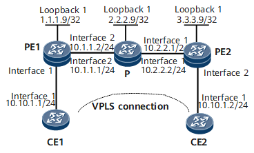
In an IP hard pipe scenario, the hard pipe function needs to be configured for PWs on the public network side. On the network shown in Figure 1, an LDP VPLS connection is configured between PE1 and PE2. VSIs must be created on PEs with specified VC labels.

Configuration Roadmap
The configuration roadmap is as follows:
Enable an IGP on the backbone network for devices to communicate with each other.
Enable MPLS and MPLS L2VPN.
Configure an LDP VPLS connection between PEs and specify VC labels
Configure IP hard pipe bandwidth reservation on main interfaces.
Data Preparation
To complete the configuration, you need the inner labels and outer labels of the static L2VC connection.
The outer label of PE1 is the same as the inner label of PE2; whereas the inner label of PE1 is the same as the outer label of PE2.
Procedure
- Assign IP addresses to interfaces on the CEs, PEs, and P as shown in Figure 1.
- Configure an IGP (OSPF in this example) on the MPLS backbone network.
- Configure basic MPLS functions on the MPLS backbone network.
# Configure PE1.
[~PE1] mpls lsr-id 1.1.1.9
[*PE1] mpls
[*PE1-mpls] mpls te
[*PE1-mpls] quit
[*PE1] interface gigabitethernet 0/1/8
[*PE1-GigabitEthernet0/1/8] mpls
[*PE1-GigabitEthernet0/1/8] mpls te
[*PE1-GigabitEthernet0/1/8] quit
[*PE1] commit
# Configure the P.
[~P] mpls lsr-id 2.2.2.9
[*P] mpls
[*P-mpls] mpls te
[*P-mpls] quit
[*P] interface gigabitethernet 0/1/0
[*P-GigabitEthernet0/1/0] mpls
[*P-GigabitEthernet0/1/0] mpls te
[*P-GigabitEthernet0/1/0] quit
[*P] interface gigabitethernet 0/1/8
[*P-GigabitEthernet0/1/8] mpls
[*P-GigabitEthernet0/1/8] mpls te
[*P-GigabitEthernet0/1/8] quit
[*P] commit
# Configure PE2.
[~PE2] mpls lsr-id 3.3.3.9
[*PE2] mpls
[*PE2-mpls] mpls te
[*PE2-mpls] quit
[*PE2] interface gigabitethernet 0/1/0
[*PE2-GigabitEthernet0/1/0] mpls
[*PE2-GigabitEthernet0/1/0] mpls te
[*PE2-GigabitEthernet0/1/0] quit
[*PE2] commit
- Configure MPLS TE tunnel interfaces.
# Configure an MPLS TE tunnel from PE1 to PE2.
[~PE1] interface Tunnel 1
[*PE1-Tunnel1] ip address unnumbered interface loopback 1
[*PE1-Tunnel1] tunnel-protocol mpls te
[*PE1-Tunnel1] destination 3.3.3.9
[*PE1-Tunnel1] mpls te tunnel-id 100
[*PE1-Tunnel1] mpls te signal-protocol cr-static
[*PE1-Tunnel1] mpls te reserved-for-binding
[*PE1-Tunnel1] mpls te bidirectional
[*PE1-Tunnel1] quit
[*PE1] commit
# Configure an MPLS TE tunnel from PE2 to PE1.
[~PE2] interface Tunnel 2
[*PE2-Tunnel2] ip address unnumbered interface loopback 1
[*PE2-Tunnel2] tunnel-protocol mpls te
[*PE2-Tunnel2] destination 1.1.1.9
[*PE2-Tunnel2] mpls te tunnel-id 200
[*PE2-Tunnel2] mpls te signal-protocol cr-static
[*PE2-Tunnel2] mpls te reserved-for-binding
[*PE2-Tunnel20] quit
[*PE2] commit
- Configure the ingress, transit node, and egress for a static bidirectional co-routed LSP.
# Configure PE1 as the ingress.
[~PE1] bidirectional static-cr-lsp ingress Tunnel1
[*PE1-bi-static-ingress-Tunnel1] forward outgoing-interface gigabitethernet0/1/8 nexthop 10.1.1.2 out-label 20
[*PE1-bi-static-ingress-Tunnel1] backward in-label 20
[*PE1-bi-static-ingress-Tunnel1] hard-pipe enable
[*PE1-bi-static-ingress-Tunnel1] quit
[*PE1] commit
# Configure the P as the transit node.
[~P] bidirectional static-cr-lsp transit lsp1
[*P-bi-static-transit-lsp1] forward in-label 20 outgoing-interface gigabitethernet0/1/0 nexthop 10.2.2.1 out-label 40
[*P-bi-static-transit-lsp1] backward in-label 16 outgoing-interface gigabitethernet0/1/8 nexthop 10.1.1.1 out-label 20
[*P-bi-static-transit-lsp1] hard-pipe enable
[*P-bi-static-transit-lsp1] quit
[*P] commit
# Configure PE2 as the egress.
[~PE2] bidirectional static-cr-lsp egress Tunnel2
[*PE2-bi-static-egress-Tunnel2] forward in-label 40 lsrid 1.1.1.9 tunnel-id 100
[*PE2-bi-static-egress-Tunnel2] backward outgoing-interface gigabitethernet0/1/0 nexthop 10.2.2.2 out-label 16
[*PE2-bi-static-egress-Tunnel2] hard-pipe enable
[*PE2-bi-static-egress-Tunnel2] quit
[*PE2] commit
- Configure a reverse tunnel attribute on the tunnel interface of PE2 and bind the tunnel interface to the static bidirectional co-routed LSP.
[~PE2] interface Tunnel 2
[~PE2-Tunnel2] mpls te passive-tunnel
[*PE2-Tunnel2] mpls te binding bidirectional static-cr-lsp egress Tunnel2
[*PE2-Tunnel2] quit
[*PE2] commit
- Enable MPLS L2VPN and configure an LDP VPLS connection on PEs.
# Configure PE1.
[~PE1] tunnel-policy policy1
[*PE1-tunnel-policy-policy1] tunnel binding destination 3.3.3.9 te Tunnel 1
[*PE1-tunnel-policy-policy1] quit
[*PE1] mpls
[*PE1-mpls] mpls l2vpn
[*PE1-l2vpn] quit
[*PE1] vsi vsi1
[*PE1-vsi-vsi1] pwsignal ldp
[*PE1-vsi-vsi1-ldp] vsi-id 1
[*PE1-vsi-vsi1-ldp] hard-pipe enable
[*PE1-vsi-vsi1-ldp] peer 3.3.3.9 tnl-policy policy1 static-upe trans 200 recv 200 hard-pipe bandwidth 112 burst-time 222
[*PE1-vsi-vsi1-ldp] quit
[*PE1-vsi-vsi1] quit
[*PE1] commit
# Configure PE2.
[~PE2] tunnel-policy policy1
[*PE2-tunnel-policy-policy1] tunnel binding destination 1.1.1.9 te Tunnel 2
[*PE2-tunnel-policy-policy1] quit
[*PE2] mpls
[*PE2-mpls] mpls l2vpn
[*PE2-l2vpn] quit
[*PE2] vsi vsi1
[*PE2-vsi-vsi1] pwsignal ldp
[*PE2-vsi-vsi1-ldp] vsi-id 1
[*PE2-vsi-vsi1-ldp] hard-pipe enable
[*PE2-vsi-vsi1-ldp] peer 1.1.1.9 tnl-policy policy1 static-upe trans 200 recv 200 hard-pipe bandwidth 112 burst-time 222
[*PE2-vsi-vsi1-ldp] quit
[*PE2-vsi-vsi1] quit
[*PE2] commit
- Configure IP hard pipe bandwidth reservation on main interfaces.
# Configure PE1.
[~PE1] interface gigabitethernet 0/1/8
[*PE1-GigabitEthernet0/1/8] qos hard-pipe share-mode bandwidth 500 outbound
[*PE1-GigabitEthernet0/1/8] quit
[*PE1] commit
# Configure the P.
[~P] interface gigabitethernet 0/1/0
[*P-GigabitEthernet0/1/0] qos hard-pipe share-mode bandwidth 500 outbound
[*P-GigabitEthernet0/1/0] quit
[*P] interface gigabitethernet 0/1/8
[*P-GigabitEthernet0/1/8] qos hard-pipe share-mode bandwidth 500 outbound
[*P-GigabitEthernet0/1/8] quit
[*P] commit
# Configure PE2.
[~PE2] interface gigabitethernet 0/1/0
[*PE2-GigabitEthernet0/1/0] qos hard-pipe share-mode bandwidth 500 outbound
[*PE2-GigabitEthernet0/1/0] quit
[*PE2] commit
- Bind a VSI to an interface.
# Configure PE1.
[~PE1] interface gigabitethernet 0/1/0
[*PE1-GigabitEthernet0/1/0] l2 binding vsi vsi1
[*PE1-GigabitEthernet0/1/0] commit
# Configure PE2.
[~PE2] interface gigabitethernet 0/1/8
[*PE2-GigabitEthernet0/1/8] l2 binding vsi vsi1
[*PE2-GigabitEthernet0/1/8] commit
- Verify the configuration.
Check VPLS connection information.
Run the display vsi command on each PE to check the hard pipe-based LDP VPLS connection information. The command output shows hard-pipe static PW information of the VPLS. The following example uses the command output on PE1.
[~PE1] display vsi name vsi1 verbose
    VSI Name               : vsi1
    Work Mode              : normal
    Administrator VSI      : no
    Isolate Spoken         : disable
    VSI Index              : 2
    PW Signaling           : ldp
    Member Discovery Style : --
    Bridge-domain Mode     : disable
    PW MAC Learn Style     : unqualify
    Encapsulation Type     : vlan
    MTU                    : 1500
    Diffserv Mode          : uniform
    Service Class          : --
    Color                  : --
    DomainId               : 255
    Domain Name            :
    Ignore AcState         : disable
    P2P VSI                : disable
    Multicast Fast Switch  : disable
    Create Time            : 0 days, 0 hours, 30 minutes, 35 seconds
    VSI State              : up
    Resource Status        : --

    VSI ID                 : 1
   *Peer Router ID         : 3.3.3.9
    Negotiation-vc-id      : 1
    primary or secondary   : primary
    ignore-standby-state   : no
    VC Label               : 200
    Peer Type              : static
    Tunnel ID              : 0x000000000300000001
    Broadcast Tunnel ID    : --
    Broad BackupTunnel ID  : --
    Tunnel Policy Name     : policy1
    CKey                   : 130
    NKey                   : 620757232
    Stp Enable             : 0
    PwIndex                : 65
    Control Word           : disable
    BFD for PW             : unavailable
    Hard-pipe bandwidth    : 112 Kbps
    Hard-pipe burst time   : 222 us

    Interface Name         : Ethernet0/1/0
    State                  : up
    Access Port            : false
    Last Up Time           : 2017/09/18 11:51:03
    Total Up Time          : 0 days, 0 hours, 26 minutes, 10 seconds

  **PW Information:

   *Peer Ip Address        : 3.3.3.9
    PW State               : up
    Local VC Label         : 200
    Remote VC Label        : 200
    Remote Control Word    : disable
    PW Type                : MEHVPLS
    Local  VCCV            : alert lsp-ping bfd
    Remote VCCV            : alert lsp-ping bfd
    Tunnel ID              : 0x000000000300000001
    Broadcast Tunnel ID    : --
    Broad BackupTunnel ID  : --
    Ckey                   : 130
    Nkey                   : 620757232
    Main PW Token          : 0x0
    Slave PW Token         : 0x0
    Tnl Type               : te
    OutInterface           : --
    Backup OutInterface    : --
    Stp Enable             : 0
    Mac Flapping           : 0
    PW Last Up Time        : 2017/09/18 12:15:40
    PW Total Up Time       : 0 days, 0 hours, 1 minutes, 33 seconds
Check whether CE1 and CE2 can communicate.
CE1 and CE2 can ping each other.
[~CE1] ping 10.10.1.2
PING 10.10.1.2: 56  data bytes, press CTRL_C to break
    Reply from 10.10.1.2: bytes=56 Sequence=1 ttl=255 time=382 ms
    Reply from 10.10.1.2: bytes=56 Sequence=2 ttl=255 time=1 ms
    Reply from 10.10.1.2: bytes=56 Sequence=3 ttl=255 time=2 ms
    Reply from 10.10.1.2: bytes=56 Sequence=4 ttl=255 time=1 ms
    Reply from 10.10.1.2: bytes=56 Sequence=5 ttl=255 time=1 ms

  --- 10.10.1.2 ping statistics ---
    5 packet(s) transmitted
    5 packet(s) received
    0.00% packet loss
    round-trip min/avg/max = 1/77/382 ms
Configuration Files
CE1 configuration file
#
 sysname CE1
#
interface GigabitEthernet0/1/0
 undo shutdown
 ip address 10.10.1.1 255.255.255.0
#
return
PE1 configuration file
#
 sysname PE1
#
mpls lsr-id 1.1.1.9
mpls
 mpls te
#
mpls l2vpn
#
tunnel-policy policy1
 tunnel binding destination 3.3.3.9 te Tunnel1
#
bidirectional static-cr-lsp ingress Tunnel1
 forward outgoing-interface GigabitEthernet0/1/8 nexthop 10.1.1.2 out-label 20
 backward in-label 20
 hard-pipe enable
#
vsi vsi1
 pwsignal ldp
  vsi-id 1
  hard-pipe enable
  peer 3.3.3.9 tnl-policy policy1 static-upe trans 200 recv 200 hard-pipe bandwidth 112 burst-time 222
 tnl-policy policy1
#
interface GigabitEthernet0/1/0
 undo shutdown
 l2 binding vsi vsi1
#
interface GigabitEthernet0/1/8
 undo shutdown
 ip address 10.1.1.1 255.255.255.0
 mpls
 mpls te
 qos hard-pipe share-mode bandwidth 500 outbound
#
interface LoopBack1
 ip address 1.1.1.9 255.255.255.255
#
interface Tunnel1
 ip address unnumbered interface loopback 1
 tunnel-protocol mpls te
 destination 3.3.3.9
 mpls te signal-protocol cr-static
 mpls te reserved-for-binding
 mpls te tunnel-id 100
 mpls te bidirectional
#
ospf 1
 area 0.0.0.0
  network 1.1.1.9 0.0.0.0
  network 10.1.1.0 0.0.0.255
#
return
P configuration file
#
 sysname P
#
mpls lsr-id 2.2.2.9
mpls
 mpls te
#
bidirectional static-cr-lsp transit lsp1
 forward in-label 20 outgoing-interface GigabitEthernet0/1/0 nexthop 10.2.2.1 out-label 40
 backward in-label 16 outgoing-interface GigabitEthernet0/1/8 nexthop 10.1.1.1 out-label 20
 hard-pipe enable
#
interface GigabitEthernet0/1/0
 undo shutdown
 ip address 10.2.2.2 255.255.255.0
 mpls
 mpls te
 qos hard-pipe share-mode bandwidth 500 outbound
#
interface GigabitEthernet0/1/8
 undo shutdown
 ip address 10.1.1.2 255.255.255.0
 mpls
 mpls te
 qos hard-pipe share-mode bandwidth 500 outbound
#
interface LoopBack1
 ip address 2.2.2.9 255.255.255.255
#
ospf 1
 area 0.0.0.0
  network 2.2.2.9 0.0.0.0
  network 10.1.1.0 0.0.0.255
  network 10.2.2.0 0.0.0.255
#
return
PE2 configuration file
#
 sysname PE2
#
mpls lsr-id 3.3.3.9
mpls
 mpls te
#
mpls l2vpn
#
tunnel-policy policy1
 tunnel binding destination 1.1.1.9 te Tunnel2
#
bidirectional static-cr-lsp egress Tunnel2
 forward in-label 40 lsrid 1.1.1.9 tunnel-id 100
 backward outgoing-interface GigabitEthernet0/1/0 nexthop 10.2.2.2 out-label 16
 hard-pipe enable
#
interface GigabitEthernet0/1/8
 undo shutdown
 l2 binding vsi vsi1
#
interface GigabitEthernet0/1/0
 undo shutdown
 ip address 10.2.2.1 255.255.255.0
 mpls
 mpls te
 qos hard-pipe share-mode bandwidth 500 outbound
#
vsi vsi1
 pwsignal ldp
  vsi-id 1
  hard-pipe enable
  peer 1.1.1.9 tnl-policy policy1 static-upe trans 200 recv 200 hard-pipe bandwidth 112 burst-time 222
 tnl-policy policy1
#
interface LoopBack1
 ip address 3.3.3.9 255.255.255.255
#
interface Tunnel2
 ip address unnumbered interface loopback 1
 tunnel-protocol mpls te
 destination 1.1.1.9
 mpls te signal-protocol cr-static
 mpls te reserved-for-binding
 mpls te tunnel-id 200
 mpls te passive-tunnel
 mpls te binding bidirectional static-cr-lsp egress Tunnel2
#
ospf 1
 area 0.0.0.0
  network 3.3.3.9 0.0.0.0
  network 10.2.2.0 0.0.0.255
#
return
CE2 configuration file
#
 sysname CE2
#
interface GigabitEthernet0/1/0
 undo shutdown
 ip address 10.10.1.2 255.255.255.0
#
return