Configuring L3VPNv4 over SRv6 TE Policy

This section describes how to configure L3VPNv4 over SRv6 TE Policy.

Usage Scenario

L3VPNv4 over SRv6 TE Policy uses public SRv6 TE Policies to carry L3VPNv4 data. The implementation of L3VPNv4 over SRv6 TE Policy involves establishing SRv6 TE Policies, advertising VPN routes, and forwarding data.

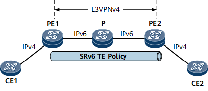
As shown in Figure 1, PE1 and PE2 communicate through an IPv6 public network. The VPN is a traditional IPv4 network. SRv6 TE Policies can be deployed on the IPv6 public network to carry L3VPNv4 services on the VPN.

Figure 1 L3VPNv4 over SRv6 TE Policy networking

Pre-configuration Tasks

Before configuring L3VPNv4 over SRv6 TE Policy, complete the following tasks:

  • Configure a link layer protocol.

  • Configure network-layer addresses for interfaces to ensure that neighboring devices are reachable at the network layer.

Procedure

  1. Configure IPv6 IS-IS on each PE and P. For details, see Configuring Basic IPv6 IS-IS Functions.
  2. Configure a VPN instance on each PE and enable the IPv4 address family for the instance.
    1. Run system-view

      The system view is displayed.

    2. Run ip vpn-instance vpn-instance-name

      A VPN instance is created, and the VPN instance view is displayed.

    3. Run ipv4-family

      The VPN instance IPv4 address family is enabled, and the view of this address family is displayed.

    4. Run route-distinguisher route-distinguisher

      An RD is configured for the VPN instance IPv4 address family.

    5. Run vpn-target vpn-target &<1-8> [ both | export-extcommunity | import-extcommunity ]

      VPN targets are configured for the VPN instance IPv4 address family.

    6. (Optional) Run default-color color-value

      The default color value is specified for the L3VPNv4 service to recurse to an SRv6 TE Policy.

      If a remote VPN route without carrying the Color Extended Community is leaked to a local VPN instance, the default color value is used for the recursion.

    7. Run commit

      The configuration is committed.

    8. Run quit

      Exit the VPN instance IPv4 address family view.

    9. Run quit

      Exit the VPN instance view.

    10. Run interface interface-type interface-number

      The view of the interface to which the VPN instance needs to be bound is displayed.

    11. Run ip binding vpn-instance vpn-instance-name

      The VPN instance is bound to the interface.

      Running the ip binding vpn-instance command deletes Layer 3 (including IPv4 and IPv6) configurations, such as IP address and routing protocol configurations, on the involved interface. If needed, reconfigure them after running the command.

    12. Run ip address ip-address { mask | mask-length }

      An IP address is configured for the interface.

      Some Layer 3 functions such as route exchange between the PE and CE can be configured only after an IP address is configured for the VPN interface on the PE.

    13. Run commit

      The configuration is committed.

    14. Run quit

      Exit the interface view.

  3. Configure IPv4 route exchange between the PE and CE. For details, see Configuring Route Exchange Between PEs and CEs.
  4. Establish an MP-IBGP peer relationship between the PEs.
    1. Run bgp { as-number-plain | as-number-dot }

      The BGP view is displayed.

    2. Run router-id ipv4-address

      A router ID is configured.

    3. Run peer ipv6-address as-number { as-number-plain | as-number-dot }

      The remote PE is configured as a peer.

    4. Run peer ipv6-address connect-interface loopback interface-number

      The interface on which a TCP connection to the specified BGP peer is established is specified.

    5. Run ipv4-family vpnv4

      The BGP VPNv4 address family view is displayed.

    6. Run peer ipv6-address enable

      The device is enabled to exchange VPN-IPv4 routes with the specified peer.

    7. Run peer ipv6-address prefix-sid

      The device is enabled to exchange IPv4 prefix SID information with a specified IPv6 peer.

    8. Run commit

      The configuration is committed.

    9. Run quit

      Exit the BGP VPNv4 address family view.

    10. Run quit

      Exit the BGP view.

  5. Configure the device to carry SIDs in VPN routes.
    1. Run segment-routing ipv6

      SRv6 is enabled, and the SRv6 view is displayed.

    2. Run encapsulation source-address ipv6-address [ ip-ttl ttl-value ]

      A source address is specified for SRv6 VPN encapsulation.

    3. Run locator locator-name [ ipv6-prefix ipv6-address prefix-length [ static static-length | args args-length ] * ]

      An SRv6 locator is configured.

    4. (Optional) Run opcode func-opcode end-dt4 vpn-instance vpn-instance-name

      A static SID operation code (opcode) is configured.

      An End.DT4 SID can be either dynamically allocated by BGP or manually configured. If you want to enable dynamic End.DT4 SID allocation using the segment-routing ipv6 locator locator-name command, skip this step.

    5. Run quit

      Exit the SRv6 locator view.

    6. Run quit

      Exit the SRv6 view.

    7. Run bgp { as-number-plain | as-number-dot }

      The BGP view is displayed.

    8. Run ipv4-family vpn-instance vpn-instance-name

      The BGP-VPN instance IPv4 address family view is displayed.

    9. Run segment-routing ipv6 locator locator-name [ auto-sid-disable ]

      The device is enabled to carry SIDs in VPN routes.

      If auto-sid-disable is not specified, dynamic SID allocation is supported. If there are static SIDs in the range of the locator specified using locator-name, the static SIDs are used. Otherwise, dynamically allocated SIDs are used.

      If auto-sid-disable is specified, BGP does not dynamically allocate SIDs.

    10. Run segment-routing ipv6 traffic-engineer [ best-effort ]

      The device is enabled to perform VPN route recursion based on the SIDs carried in the routes.

      If an SRv6 BE path exists on the network, you can set the best-effort parameter, allowing the SRv6 BE path to function as a best-effort path in the case of an SRv6 TE Policy fault.

    11. Run commit

      The configuration is committed.

    12. Run quit

      Exit the BGP-VPN instance IPv4 address family view.

    13. Run quit

      Exit the BGP view.

  6. Configure an SRv6 TE Policy. For details, see Configuring an SRv6 TE Policy (Manual Configuration) or Configuring an SRv6 TE Policy (Dynamic Delivery by a Controller).
  7. Configure VPNv4 routes to recurse to the SRv6 TE Policy.
    1. Run route-policy route-policy-name { deny | permit } node node

      A route-policy node is created, and the route-policy view is displayed.

    2. (Optional) Configure an if-match clause as a route-policy filter criterion. You can add or modify the Color Extended Community only for a route-policy that meets the filter criterion.

      For details about the configuration, see (Optional) Configuring an if-match Clause.

    3. Run apply extcommunity color color

      The BGP Color Extended Community is configured.

    4. Run quit

      Exit the route-policy view.

    5. Run bgp as-number

      The BGP view is displayed.

    6. Run ipv4-family vpnv4

      The BGP VPNv4 address family view is displayed.

    7. Run peer ipv6-address route-policy route-policy-name { import | export }

      A BGP import or export route-policy is configured.

    8. Run quit

      Exit the BGP VPNv4 address family view.

    9. Run quit

      Exit the BGP view.

    10. Run tunnel-policy policy-name

      A tunnel policy is created, and the tunnel policy view is displayed.

    11. (Optional) Run description description-information

      A description is configured for the tunnel policy.

    12. Run tunnel select-seq ipv6 srv6-te-policy load-balance-number loadBalanceNumber

      The tunnel selection sequence and the number of tunnels for load balancing are configured.

    13. Run quit

      Exit the tunnel policy view.

    14. Run ip vpn-instance vpn-instance-name

      The VPN instance view is displayed.

    15. Run ipv4-family

      The VPN instance IPv4 address family view is displayed.

    16. Run tnl-policy policy-name

      A tunnel policy is applied to the VPN instance IPv4 address family.

    17. Run commit

      The configuration is committed.

Verifying the Configuration

After configuring L3VPNv4 over SRv6 TE Policy, verify the configuration.

  • Run the display segment-routing ipv6 locator [ locator-name ] verbose command to check SRv6 locator information.

  • Run the display segment-routing ipv6 local-sid { end | end-x | end-dt4 } [ sid ] forwarding command to check information about the SRv6 local SID table.

  • Run the display ip vpn-instance vpn-instance-name tunnel-info nexthop nexthopIpv6Addr command to check information about the tunnel to which the route with the specified next hop recurses in each address family of the current VPN instance.
  • Run the ping srv6-te policy { policy-name policyname | endpoint-ip endpointipv6 color colorid | binding-sid bsid } [ end-op endop ] [ -a sourceaddr6 | -c count | -m interval | -s packetsize | -t timeout | -tc tc | -h hoplimit ] * command with the policy-name policyname, endpoint-ip endpointipv6 color colorid, or binding-sid bsid parameter to initiate a ping operation on the specified SRv6 TE Policy for connectivity check.
  • Run the ping command to check the connectivity between CEs.

Copyright © Huawei Technologies Co., Ltd.
Next topic >