Example for Configuring an NG MVPN (PIM-SM RPT Setup Not Across the Public Network) with (*, G) Join to Carry Multicast Traffic over an RSVP-TE P2MP LSP
This section provides an example for configuring an NG MVPN (PIM-SM RPT setup not across the public network) with (*, G) Join to carry multicast traffic over an RSVP-TE P2MP LSP.
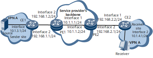
Networking Requirements
On the NG MVPN network shown in Figure 1, RSVP-TE tunnels have been deployed to carry BGP/MPLS IP VPN services. In this NG MVPN example, users send PIM-SM (*, G) Join messages to join a multicast group. Configure PIM-SM RPTs to be set up not across the public network.
Configuration Roadmap
The configuration roadmap is as follows:
Configure BGP/MPLS IP VPN and ensure that unicast VPN services are properly transmitted.
Enable P2MP TE globally and configure a P2MP TE template on each PE so that the PEs can use RSVP-TE to establish a P2MP LSP.
Establish BGP MVPN peer relationships between the PEs so that the PEs can use BGP to exchange BGP A-D and BGP C-multicast routes (C is short for Customer. C-multicast refers to multicast routes from the CE).
Configure PE1 to use MPLS TE to establish an I-PMSI tunnel so that an RSVP-TE P2MP LSP can be triggered. Configure PIM-SM RPTs to be set up not across the public network.
Configure PIM-SM on the PE interfaces bound to VPN instances and on the CE interfaces connecting to PEs to allow a VPN multicast routing table to be established to guide multicast traffic forwarding.
Configure a candidate-rendezvous point (C-RP) and candidate-bootstrap router (C-BSR) on each PE.

Because PIM BSR messages cannot be transmitted over BGP, you must configure a C-RP and C-BSR on each PE and use BGP Source Active AD routes to implement Anycast RP.
If PIM-SM RPT setup is not across the public network in the NG MVPN scenario, you can use either static or dynamic RPs. Either a PE or CE can be configured as an RP. If a CE serves as the private network RP, configure the CE and PE to establish an MSDP peer relationship. For details about the MSDP peer configuration, see Configuring MSDP Peers. In addition, you need to configure import and export of MSDP SA messages and BGP Source Active AD routes. For configuration details, see Configuring a P2MP LSP to Carry Multicast Traffic.
Configure IGMP on the interfaces connecting a multicast device to a user network segment to allow the device to manage multicast group members on the network segment.
Data Preparation
To complete the configuration, you need the following data:
Loopback1 interface addresses of PE1 and PE2 (1.1.1.1 and 2.2.2.2); Loopback2 interface address (4.4.4.4)
OSPF process on the public network (process 1) in Area 0; OSPF multi-process (process 2) in Area 0
MPLS LSR IDs of PE1 and PE2 (1.1.1.1 and 2.2.2.2)
AS number of PEs (AS 100)
MVPN IDs of PE1 and PE2 (1.1.1.1 and 2.2.2.2)
VPN instance names (VPNA), RDs (100:1 and 200:1), and VPN targets of VPN instances (3:3)
Procedure
- Configure BGP/MPLS IP VPN.
- Configure an IGP to interconnect devices on the BGP/MPLS IP VPN backbone network.
OSPF is used in this example. For configuration details, see Configuration Files in this section.
- Configure an IGP to interconnect devices on the BGP/MPLS IP VPN backbone network.
- Enable P2MP TE globally and configure a P2MP TE template.
# Configure PE1.
[~PE1] mpls
[*PE1-mpls] mpls te p2mp-te
[*PE1-mpls] quit
[*PE1] mpls te p2mp-template t1
[*PE1-te-p2mp-template-t1] quit
[*PE1] commit
# Configure PE2.
[~PE2] mpls
[*PE2-mpls] mpls te p2mp-te
[*PE2-mpls] quit
[*PE2] commit
- Establish a BGP MVPN peer relationship between the PEs.
# Configure PE1.
[~PE1] bgp 100
[*PE1-bgp] ipv4-family mvpn
[*PE1-bgp-af-mvpn] peer 2.2.2.2 enable
[*PE1-bgp-af-mvpn] quit
[*PE1-bgp] quit
[*PE1] commit
The configuration of PE2 is similar to the configuration of PE1. For configuration details, see Configuration Files in this section.
After the configurations are complete, run the display bgp mvpn all peer command on the PEs. The command output shows that PE1 has established a BGP MVPN peer relationship with PE2. The following example uses the command output on PE1:
[~PE1] display bgp mvpn all peer BGP local router ID : 1.1.1.1 Local AS number : 100 Total number of peers : 1 Peers in established state : 1 Peer V AS MsgRcvd MsgSent OutQ Up/Down State PrefRcv 2.2.2.2 4 100 17 17 0 00:05:31 Established 2 - Configure each PE to use RSVP-TE to establish an I-PMSI tunnel. Configure PIM-SM RPTs to be set up not across the public network.
To configure PIM-SM RPTs to be set up not across the public network, run the spt-only mode command. PEs in the same VPN instance must use the same PIM-SM RPT setup mode.
# Configure PE1.
[~PE1] multicast mvpn 1.1.1.1
[*PE1] ip vpn-instance VPNA
[*PE1-vpn-instance-VPNA] ipv4-family
[*PE1-vpn-instance-VPNA-af-ipv4] multicast routing-enable
[*PE1-vpn-instance-VPNA-af-ipv4] mvpn
[*PE1-vpn-instance-VPNA-af-ipv4-mvpn] sender-enable
[*PE1-vpn-instance-VPNA-af-ipv4-mvpn] c-multicast signaling bgp
[*PE1-vpn-instance-VPNA-af-ipv4-mvpn] spt-only mode
[*PE1-vpn-instance-VPNA-af-ipv4-mvpn] ipmsi-tunnel
[*PE1-vpn-instance-VPNA-af-ipv4-mvpn-ipmsi] mpls te
[*PE1-vpn-instance-VPNA-af-ipv4-mvpn-ipmsi-mpls-te] p2mp-template t1
[*PE1-vpn-instance-VPNA-af-ipv4-mvpn-ipmsi-mpls-te] quit
[*PE1-vpn-instance-VPNA-af-ipv4-mvpn-ipmsi] quit
[*PE1-vpn-instance-VPNA-af-ipv4-mvpn] quit
[*PE1-vpn-instance-VPNA-af-ipv4] quit
[*PE1-vpn-instance-VPNA] quit
[*PE1] commit
# Configure PE2.
[~PE2] multicast mvpn 2.2.2.2
[*PE2] ip vpn-instance VPNA
[*PE2-vpn-instance-VPNA] ipv4-family
[*PE2-vpn-instance-VPNA-af-ipv4] multicast routing-enable
[*PE2-vpn-instance-VPNA-af-ipv4] mvpn
[*PE2-vpn-instance-VPNA-af-ipv4-mvpn] spt-only mode
[*PE2-vpn-instance-VPNA-af-ipv4-mvpn] c-multicast signaling bgp
[*PE2-vpn-instance-VPNA-af-ipv4-mvpn] quit
[*PE2-vpn-instance-VPNA-af-ipv4] quit
[*PE2-vpn-instance-VPNA] quit
[*PE2] commit
- Configure PIM-SM.
# Configure PE1.
[~PE1] interface gigabitethernet0/1/1
[*PE1-GigabitEthernet0/1/1] pim sm
[*PE1-GigabitEthernet0/1/1] quit
[*PE1] commit
The configuration of PE2 is similar to the configuration of PE1. For configuration details, see Configuration Files in this section.
# Configure CE1.
[~CE1] multicast routing-enable
[*CE1] interface gigabitethernet0/1/0
[*CE1-GigabitEthernet0/1/0] pim sm
[*CE1-GigabitEthernet0/1/0] quit
[*CE1] interface gigabitethernet0/1/1
[*CE1-GigabitEthernet0/1/1] pim sm
[*CE1-GigabitEthernet0/1/1] quit
[*CE1] commit
The configuration of CE2 is similar to the configuration of CE1. For configuration details, see Configuration Files in this section.
- Configure a C-BSR and C-RP.
To use a static RP, run the static-rp rp-address command to configure an RP address on each PE and CE.
# Configure PE1.
[~PE1] interface LoopBack2
[*PE1-LoopBack2] ip binding vpn-instance VPNA
[*PE1-LoopBack2] ip address 4.4.4.4 255.255.255.255
[*PE1-LoopBack2] pim sm
[*PE1-LoopBack2] quit
[*PE1] pim vpn-instance VPNA
[*PE1-pim-VPNA] c-bsr LoopBack2
[*PE1-pim-VPNA] c-rp LoopBack2
[*PE1-pim-VPNA] quit
[*PE1] commit
# Configure PE2.
[~PE2] interface LoopBack2
[*PE2-LoopBack2] ip binding vpn-instance VPNA
[*PE2-LoopBack2] ip address 4.4.4.4 255.255.255.255
[*PE2-LoopBack2] pim sm
[*PE2-LoopBack2] quit
[*PE2] pim vpn-instance VPNA
[*PE2-pim-VPNA] c-bsr LoopBack2
[*PE2-pim-VPNA] c-rp LoopBack2
[*PE2-pim-VPNA] quit
[*PE2] commit
- Configure IGMP.
[~CE2] interface gigabitethernet0/1/1
[*CE2-GigabitEthernet0/1/1] pim sm
[*CE2-GigabitEthernet0/1/1] igmp enable
[*CE2-GigabitEthernet0/1/1] igmp static-group 225.0.0.1
[*CE2-GigabitEthernet0/1/1] quit
[*CE2] commit
- Verify the configuration.
After the configurations are complete, an NG MVPN with (*, G) join is configured. In this example, multicast source (10.1.3.0/24) in the PIM-SM domain sends multicast traffic to multicast group G (225.0.0.1). The receiver joins multicast group G and receives multicast traffic from this group. Run the display pim routing-table command to check whether multicast routing entries are correctly generated and whether the NG MVPN with (*, G) join is successfully configured.
Run the display pim vpn-instance routing-table command on PE1 and PE2 to check the PIM routing table of a VPN instance.
[~PE1] display pim vpn-instance VPNA routing-table
 VPN-Instance: VPNA
 Total 0 (*, G) entry; 1 (S, G) entry

 (10.1.3.100, 225.0.0.1)
     RP: 4.4.4.4 (local)
     Protocol: pim-sm, Flag: SPT 2MSDP ACT SG_RCVR 2BGP
     UpTime: 00:10:43
     Upstream interface: Gigabitethernet0/1/1
         Upstream neighbor: 192.168.1.1
         RPF prime neighbor: 192.168.1.1
     Downstream interface(s) information:
     Total number of downstreams: 1
        1: pseudo
             Protocol: BGP, UpTime: 00:01:46, Expires: -
[~PE2] display pim vpn-instance VPNA routing-table
 VPN-Instance: VPNA
 Total 1 (*, G) entry; 1 (S, G) entry

 (*, 225.0.0.1)
     RP: 4.4.4.4 (local)
     Protocol: pim-sm, Flag: WC
     UpTime: 00:03:17
     Upstream interface: Register
         Upstream neighbor: NULL
         RPF prime neighbor: NULL
     Downstream interface(s) information:
     Total number of downstreams: 1
        1: Gigabitethernet0/1/1
             Protocol: pim-sm, UpTime: 00:03:17, Expires: 00:03:13

 (10.1.3.100, 225.0.0.1)
     RP: 4.4.4.4 (local)
     Protocol: pim-sm, Flag: SPT ACT BGP
     UpTime: 00:03:17
     Upstream interface: through-BGP
         Upstream neighbor: 1.1.1.1
         RPF prime neighbor: 1.1.1.1
     Downstream interface(s) information:
     Total number of downstreams: 1
        1: Gigabitethernet0/1/1
             Protocol: pim-sm, UpTime: 00:03:17, Expires: 00:03:18
Run the display pim routing-table command on CE1 and CE2 to check their PIM routing tables.
[~CE1] display pim routing-table
 VPN-Instance: public net
 Total 0 (*, G) entry; 1 (S, G) entry

 (10.1.3.100, 225.0.0.1)
     RP: 4.4.4.4
     Protocol: pim-sm, Flag: SPT LOC ACT
     UpTime: 04:29:13
     Upstream interface: Gigabitethernet0/1/0
         Upstream neighbor: NULL
         RPF prime neighbor: NULL
     Downstream interface(s) information:
     Total number of downstreams: 1
        1: Gigabitethernet0/1/1
             Protocol: pim-sm, UpTime: 00:02:39, Expires: 00:02:45
[~CE2] display pim routing-table
 VPN-Instance: public net
 Total 1 (*, G) entry; 1 (S, G) entry

 (*, 225.0.0.1)
     RP: 4.4.4.4
     Protocol: pim-sm, Flag: WC
     UpTime: 04:14:33
     Upstream interface: Gigabitethernet0/1/0
         Upstream neighbor: 192.168.2.1
         RPF prime neighbor: 192.168.2.1
     Downstream interface(s) information:
     Total number of downstreams: 1
        1: Gigabitethernet0/1/1
             Protocol: static, UpTime: 04:14:33, Expires: -

 (10.1.3.100, 225.0.0.1)
     RP: 4.4.4.4
     Protocol: pim-sm, Flag: SPT ACT
     UpTime: 00:02:59
     Upstream interface: Gigabitethernet0/1/0
         Upstream neighbor: 192.168.2.1
         RPF prime neighbor: 192.168.2.1
     Downstream interface(s) information:
     Total number of downstreams: 1
        1: Gigabitethernet0/1/1
             Protocol: pim-sm, UpTime: 00:02:59, Expires: -
The command output shows that PE2 does not send (*, G) information to PE1 (sender PE) and PE1 does not create (*, G) entries. (S, G) PIM routing entries have been created successfully, and the receiver can receive multicast data from the multicast source 10.1.3.100.
Run the display mvpn vpn-instance vpn-instance-name ipmsi verbose command on the PEs to check I-PMSI tunnel establishment. The following example uses the command output on PE1:
[~PE1] display mvpn vpn-instance VPNA ipmsi verbose
MVPN local I-PMSI information for VPN-Instance: VPNA
Tunnel type: RSVP-TE P2MP LSP
Tunnel state: Up
P2MP ID: 0x1010101
Tunnel ID: 32769
Extended tunnel ID: 1.1.1.1
Root: 1.1.1.1 (local)
Leaf:
  1: 2.2.2.2
Total number of (S, G): 1
    1. (10.1.3.100, 225.0.0.1)
The command output shows that an RSVP-TE P2MP has been established, with PE1 as the root node and PE2 as leaf nodes.
Configuration Files
CE1 configuration file
#
sysname CE1
#
multicast routing-enable
#
interface GigabitEthernet0/1/0
 undo shutdown
 ip address 10.1.3.1 255.255.255.0
 pim sm
#
interface GigabitEthernet0/1/1
 undo shutdown
 ip address 192.168.1.1 255.255.255.0
 pim sm
#
ospf 2
 area 0.0.0.0
  network 10.1.3.0 0.0.0.255
  network 192.168.1.0 0.0.0.255
#
return
PE1 configuration file
#
sysname PE1
#
multicast mvpn 1.1.1.1
#
ip vpn-instance VPNA
 ipv4-family
  route-distinguisher 100:1
  apply-label per-instance
  vpn-target 3:3 export-extcommunity
  vpn-target 3:3 import-extcommunity
  multicast routing-enable
  mvpn
   sender-enable
   c-multicast signaling bgp
   spt-only mode
   ipmsi-tunnel
    mpls te
     p2mp-template t1
#
mpls lsr-id 1.1.1.1
#
mpls
 mpls te
 mpls te p2mp-te
 mpls rsvp-te
 mpls te cspf
#
mpls te p2mp-template t1
#
mpls ldp
#
interface GigabitEthernet0/1/0
 undo shutdown
 ip address 10.1.1.1 255.255.255.0
 mpls
 mpls te
 mpls rsvp-te
#
interface GigabitEthernet0/1/1
 undo shutdown
 ip binding vpn-instance VPNA
 ip address 192.168.1.2 255.255.255.0
 pim sm
#
interface LoopBack1
 ip address 1.1.1.1 255.255.255.255
#
interface LoopBack2
 ip binding vpn-instance VPNA
 ip address 4.4.4.4 255.255.255.255
 pim sm
#
bgp 100
 peer 2.2.2.2 as-number 100
 peer 2.2.2.2 connect-interface LoopBack1
 #
 ipv4-family unicast
  undo synchronization
  peer 2.2.2.2 enable
 #
 ipv4-family mvpn
  policy vpn-target
  peer 2.2.2.2 enable
#
 ipv4-family vpnv4
  policy vpn-target
  peer 2.2.2.2 enable
 #
 ipv4-family vpn-instance VPNA
  import-route ospf 2
#
ospf 1
 opaque-capability enable
 area 0.0.0.0
  network 1.1.1.1 0.0.0.0
  network 10.1.1.0 0.0.0.255
  mpls-te enable
#
ospf 2 vpn-instance VPNA
 import-route bgp
 area 0.0.0.0
  network 4.4.4.4 0.0.0.0
  network 192.168.1.0 0.0.0.255
#
pim vpn-instance VPNA
 c-bsr LoopBack2
 c-rp LoopBack2
#
return
CE2 configuration file
#
sysname CE2
#
multicast routing-enable
#
interface GigabitEthernet0/1/0
 undo shutdown
 ip address 192.168.2.2 255.255.255.0
 pim sm
#
interface GigabitEthernet0/1/1
 undo shutdown
 ip address 10.1.4.1 255.255.255.0
 pim sm
 igmp enable
 igmp static-group 225.0.0.1
#
ospf 2
 area 0.0.0.0
  network 10.1.4.0 0.0.0.255
  network 192.168.2.0 0.0.0.255
#
return
PE2 configuration file
#
sysname PE2
#
multicast mvpn 2.2.2.2
#
ip vpn-instance VPNA
 ipv4-family
  route-distinguisher 200:1
  apply-label per-instance
  vpn-target 3:3 export-extcommunity
  vpn-target 3:3 import-extcommunity
  multicast routing-enable
  mvpn
   c-multicast signaling bgp
   spt-only mode
#
mpls lsr-id 2.2.2.2
#
mpls
 mpls te
 mpls te p2mp-te
 mpls rsvp-te
 mpls te cspf
#
mpls ldp
#
interface GigabitEthernet0/1/0
 undo shutdown
 ip address 10.1.1.2 255.255.255.0
 mpls
 mpls te
 mpls rsvp-te
#
interface GigabitEthernet0/1/1
 undo shutdown
 ip binding vpn-instance VPNA
 ip address 192.168.2.1 255.255.255.0
 pim sm
#
interface LoopBack1
 ip address 2.2.2.2 255.255.255.255
#
interface LoopBack2
 ip binding vpn-instance VPNA
 ip address 4.4.4.4 255.255.255.255
 pim sm
#
bgp 100
 peer 1.1.1.1 as-number 100
 peer 1.1.1.1 connect-interface LoopBack1
 #
 ipv4-family unicast
  undo synchronization
  peer 1.1.1.1 enable
 #
 ipv4-family mvpn
  policy vpn-target
  peer 1.1.1.1 enable
 #
 ipv4-family vpnv4
  policy vpn-target
  peer 1.1.1.1 enable
 #
 ipv4-family vpn-instance VPNA
  import-route ospf 2
#
ospf 1
 opaque-capability enable
 area 0.0.0.0
  network 2.2.2.2 0.0.0.0
  network 10.1.1.0 0.0.0.255
  mpls-te enable
#
ospf 2 vpn-instance VPNA
 import-route bgp
 area 0.0.0.0
  network 4.4.4.4 0.0.0.0
  network 192.168.2.0 0.0.0.255
#
pim vpn-instance VPNA
 c-bsr LoopBack2
 c-rp LoopBack2
#
return