Example for Configuring an Intra-AS NG MVPN with Segmented Tunnels
This section provides an example for configuring an intra-AS NG MVPN to carry multicast traffic over segmented tunnels.
Networking Requirements
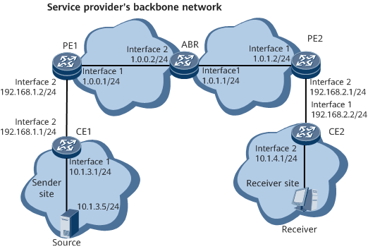
NG MVPN is deployed on the service provider's backbone network to solve multicast service issues related to traffic congestion, transmission reliability, and data security. On the segmented NG MVPN shown in Figure 1, RSVP-TE P2MP and mLDP LSPs have been deployed in the backbone network's areas to carry BGP/MPLS IP VPN services. The service provider wants to provide MVPN services for users based on the existing network. To meet this requirement, configure a segmented NG MVPN to carry multicast traffic over the RSVP-TE P2MP and mLDP LSPs.

Configuration Roadmap
The configuration roadmap is as follows:
Configure BGP/MPLS IP VPN and ensure that unicast VPN services are properly transmitted.
Establish a BGP MVPN peer relationship between the PEs so that the PEs can use BGP to exchange A-D and C-multicast routes.
Configure a route-policy on each PE and the ABR to establish BGP LSPs.
Configure the ABR as an RR to help PE1 and PE2 obtain the route destined for each other's loopback interface.
Configure PE1 to use RSVP-TE to establish an Inclusive-Provider Multicast Service Interface (I-PMSI) tunnel so that an RSVP-TE P2MP LSP from PE1 to the ABR can be triggered.
Configure the ABR to use mLDP to establish a stitched tunnel to PE2 so that an mLDP P2MP LSP can be triggered.
Configure PIM on the PE interfaces bound to VPN instances and on the CE interfaces connecting to PEs to allow a VPN multicast routing table to be established to guide multicast traffic forwarding.
Configure IGMP on the interfaces connecting a multicast device to a user network segment to allow the device to manage multicast group members on the network segment.
Data Preparation
To complete the configuration, you need the following data:
OSPF process ID on PE1 and the ABR: 10
On PE2 and the ABR: IS-IS process ID (2), IS-IS level (Level-2), system ID of PE2 (45.0005.0005.0006.00), and system ID of the ABR (45.0005.0005.0005.00)
- VPN instance name on PE1 and PE2: vpn1 (other data is shown in )
Table 1 Data needed for each device Device
Loopback 0 Interface Address
MPLS LSR-ID
MVPN ID
RD
VPN-Target
AS Number
PE1
1.1.1.1
1.1.1.1
1.1.1.1
1:1
200:1
AS100
ABR
2.2.2.2
2.2.2.2
2.2.2.2
-
-
AS100
PE2
1.1.2.2
1.1.2.2
1.1.2.2
6:1
200:1
AS100
Procedure
- Configure BGP/MPLS IP VPN.
- Establish BGP MVPN peer relationships on the PEs and ABR.
# Configure PE1.
[~PE1] bgp 100
[*PE1-bgp] ipv4-family mvpn
[*PE1-bgp-af-mvpn] policy vpn-target
[*PE1-bgp-af-mvpn] peer 2.2.2.2 enable
[*PE1-bgp-af-mvpn] quit
[*PE1-bgp] quit
[*PE1] commit
# Configure PE2.
[~PE2] bgp 100
[*PE2-bgp] ipv4-family mvpn
[*PE2-bgp-af-mvpn] policy vpn-target
[*PE2-bgp-af-mvpn] peer 2.2.2.2 enable
[*PE2-bgp-af-mvpn] quit
[*PE2-bgp] quit
[*PE2] commit
# Configure the ABR.
[~ABR] bgp 100
[*ABR-bgp] ipv4-family mvpn
[*ABR-bgp-af-mvpn] reflect change-path-attribute
[*ABR-bgp-af-mvpn] undo policy vpn-target
[*ABR-bgp-af-mvpn] peer 1.1.1.1 enable
[*ABR-bgp-af-mvpn] peer 1.1.2.2 enable
[*ABR-bgp-af-mvpn] quit
[*ABR-bgp] quit
[*ABR] commit
- Configure the ABR as an RR to help PE1 and PE2 obtain the route destined for each other's loopback interface.
# Configure the ABR.
[~ABR] bgp 100
[*ABR-bgp] ipv4-family mvpn
[*ABR-bgp-af-mvpn] peer 1.1.1.1 reflect-client
[*ABR-bgp-af-mvpn] peer 1.1.2.2 reflect-client
[*ABR-bgp-af-mvpn] quit
[*ABR-bgp] quit
[*ABR] commit
- Configure a route-policy on each PE and the ABR to establish BGP LSPs.
# Configure a route-policy for advertising matching routes to PE1's BGP peer.
[~PE1] route-policy policy2 permit node 2
[*PE1-route-policy] apply mpls-label
[*PE1-route-policy] quit
[*PE1] bgp 100
[*PE1-bgp] ipv4-family unicast
[*PE1-bgp-af-ipv4] peer 2.2.2.2 route-policy policy2 export
[*PE1-bgp-af-ipv4] quit
[*PE1-bgp] quit
[*PE1] commit
The configuration of PE2 is similar to that of PE1.
# Configure a route-policy for advertising matching routes to the ABR's BGP peer.
[~ABR] route-policy policy2 permit node 1
[*ABR-route-policy] apply mpls-label
[*ABR-route-policy] quit
[*ABR] bgp 100
[*ABR-bgp] ipv4-family unicast
[*ABR-bgp-af-ipv4] peer 1.1.1.1 route-policy policy2 export
[*ABR-bgp-af-ipv4] peer 1.1.2.2 route-policy policy2 export
[*ABR-bgp-af-ipv4] quit
[*ABR-bgp] quit
[*ABR] commit
- Configure NG MVPN to support intra-AS inter-area segmented tunnels.
# Configure PE1.
[*PE1] ip vpn-instance vpn1
[*PE1-vpn-instance-vpn1] ipv4-family
[*PE1-vpn-instance-vpn1-af-ipv4] multicast routing-enable
[*PE1-vpn-instance-vpn1-af-ipv4] mvpn
[*PE1-vpn-instance-vpn1-af-ipv4-mvpn] inter-area-segmented enable
[*PE1-vpn-instance-vpn1-af-ipv4-mvpn] quit
[*PE1-vpn-instance-vpn1-af-ipv4] quit
[*PE1-vpn-instance-vpn1] quit
[*PE1] commit
# Configure the ABR.
[~ABR] multicast mvpn inter-area-segmented enable
[*ABR] commit
- Configure PE1 to use RSVP-TE to establish an I-PMSI tunnel to the ABR, and configure the ABR to use mLDP to establish a stitched tunnel to PE2.
# Configure PE1.
[~PE1] multicast mvpn 1.1.1.1
[*PE1] ip vpn-instance vpn1
[*PE1-vpn-instance-vpn1] ipv4-family
[*PE1-vpn-instance-vpn1-af-ipv4] mvpn
[*PE1-vpn-instance-vpn1-af-ipv4-mvpn] sender-enable
[*PE1-vpn-instance-vpn1-af-ipv4-mvpn] c-multicast signaling bgp
[*PE1-vpn-instance-vpn1-af-ipv4-mvpn] inter-area-segmented enable
[*PE1-vpn-instance-vpn1-af-ipv4-mvpn] ipmsi-tunnel
[*PE1-vpn-instance-vpn1-af-ipv4-mvpn-ipmsi] mpls te
[*PE1-vpn-instance-vpn1-af-ipv4-mvpn-ipmsi-mpls-te] p2mp-template t1
[*PE1-vpn-instance-vpn1-af-ipv4-mvpn-ipmsi-mpls-te] quit
[*PE1-vpn-instance-vpn1-af-ipv4-mvpn-ipmsi] quit
[*PE1-vpn-instance-vpn1-af-ipv4-mvpn] quit
[*PE1-vpn-instance-vpn1-af-ipv4] quit
[*PE1-vpn-instance-vpn1] quit
[*PE1] commit
# Configure the ABR.
[~ABR] multicast mvpn 2.2.2.2
[*ABR] route-policy rp1 permit node 1
[*ABR-route-policy-rp1]apply stitch-pmsi mldp
[*ABR-route-policy-rp1]quit
[~ABR] bgp 100
[*ABR-bgp] ipv4-family mvpn
[*ABR-bgp-af-mvpn] peer 1.1.2.2 route-policy rp1 export
[*ABR-bgp-af-mvpn] quit
[*ABR-bgp] quit
[*ABR] commit
# Configure PE2.
[~PE2] multicast mvpn 1.1.2.2
[*PE2] ip vpn-instance vpn1
[*PE2-vpn-instance-vpn1] ipv4-family
[*PE2-vpn-instance-vpn1-af-ipv4] mvpn
[*PE2-vpn-instance-vpn1-af-ipv4-mvpn] c-multicast signaling bgp
[*PE2-vpn-instance-vpn1-af-ipv4-mvpn] quit
[*PE2-vpn-instance-vpn1-af-ipv4] quit
[*PE2-vpn-instance-vpn1] quit
[*PE2] commit
After the configuration is complete, run the display mvpn inter-region-segmented ipmsi command on the ABR to check I-PMSI tunnel information.
[~ABR] display mvpn inter-region-segmented  ipmsi
Inter-region-segmented I-PMSI routes: total 1
I-PMSI(RD:OrigIP): 1:1: 1.1.1.1
Received Upstream I-PMSI: Tunnel type: RSVP-TE P2MP LSP, P2MP-ID: 0x02020202, Tunnel ID: 49281, Extended Tunnel ID: 1.1.1.1
Leaf:
  1: 2.2.2.2 (local)
Advertised Downstream I-PMSI(Policy: rp1): Tunnel type: mLDP P2MP LSP, Root-IP: 2.2.2.2, Opaque value: 0x0100040000A001
Leaf:
  1: 1.1.2.2
The command output shows that an RSVP-TE P2MP LSP has been established, with PE1 as the root node and the ABR as a leaf node. The command output also shows that an mLDP P2MP LSP has been established, with the ABR as the root node and PE2 as a leaf node.
- Configure an S-PMSI tunnel.
# Configure PE1.
[*PE1] ip vpn-instance vpn1
[*PE1-vpn-instance-vpn1] ipv4-family
[*PE1-vpn-instance-vpn1-af-ipv4] mvpn
[*PE1-vpn-instance-vpn1-af-ipv4-mvpn] spmsi-tunnel
[*PE1-vpn-instance-vpn1-af-ipv4-mvpn-ipmsi-mpls-te] group 225.1.1.1 255.255.255.255 source 10.1.3.5 255.255.255.255 rsvp-te p2mp-template t1
[*PE1-vpn-instance-vpn1-af-ipv4-mvpn-spmsi-mpls-te] quit
[*PE1-vpn-instance-vpn1-af-ipv4-mvpn-ipmsi] quit
[*PE1-vpn-instance-vpn1-af-ipv4-mvpn] quit
[*PE1-vpn-instance-vpn1-af-ipv4] quit
[*PE1-vpn-instance-vpn1] quit
[*PE1] commit
- Configure PIM.
# Configure PE1.
[*PE1] interface gigabitethernet0/1/1
[*PE1-GigabitEthernet0/1/1] pim sm
[*PE1-GigabitEthernet0/1/1] quit
[*PE1] commit
# Configure CE1.
[~CE1] multicast routing-enable
[*CE1] interface gigabitethernet0/1/0
[*CE1-GigabitEthernet0/1/0] pim sm
[*CE1-GigabitEthernet0/1/0] quit
[*CE1] interface gigabitethernet0/1/1
[*CE1-GigabitEthernet0/1/1] pim sm
[*CE1-GigabitEthernet0/1/1] quit
[*CE1] commit
# Configure PE2.
[*PE2] interface gigabitethernet0/1/1
[*PE2-GigabitEthernet0/1/1] pim sm
[*PE2-GigabitEthernet0/1/1] quit
[*PE2] commit
# Configure CE2.
[~CE2] multicast routing-enable
[*CE2] interface gigabitethernet0/1/0
[*CE2-GigabitEthernet0/1/0] pim sm
[*CE2-GigabitEthernet0/1/0] quit
[*CE2] interface gigabitethernet0/1/1
[*CE2-GigabitEthernet0/1/1] pim sm
[*CE2-GigabitEthernet0/1/1] quit
[*CE2] commit
- Configure IGMP.
# Configure CE2.
[~CE2] interface gigabitethernet0/1/1
[*CE2-GigabitEthernet0/1/1] igmp enable
[*CE2-GigabitEthernet0/1/1] igmp version 3
[*CE2-GigabitEthernet0/1/1] quit
[*CE2] commit
- Verify the configuration.
After the configuration is complete, segmented NG MVPN functions have been configured. If CE2 has access users, CE1 can use the BGP/MPLS IP VPN to forward multicast data to the users. Configure users on CE2 to send IGMP Report messages and the multicast source 10.1.3.5 to send multicast data. Then, check multicast routing entries to verify whether the segmented NG MVPN is configured successfully.
Run the display pim routing-table command on CE2 and CE1 to check the PIM routing table. Run the display pim vpn-instance routing-table command on PE2, the ABR, and PE1 to check the PIM routing tables of the VPN instance.
[~CE2] display pim routing-table
 VPN-Instance: public net
 Total 0 (*, G) entry; 1 (S, G) entry

 (10.1.3.5, 225.1.1.1)
     RP: NULL
     Protocol: pim-sm, Flag: SPT SG_RCVR ACT
     UpTime: 08:48:25
     Upstream interface: GigabitEthernet0/1/0
         Upstream neighbor: 192.168.2.1
         RPF prime neighbor: 192.168.2.1
     Downstream interface(s) information:
     Total number of downstreams: 1
        1: GigabitEthernet0/1/1
             Protocol: igmp, UpTime: 08:48:25, Expires: -
[~PE2] display pim vpn-instance vpn1 routing-table
 VPN-Instance: vpn1
 Total 0 (*, G) entry; 1 (S, G) entry

 (10.1.3.5, 225.1.1.1)
     RP: NULL
     Protocol: pim-sm, Flag: SPT ACT
     UpTime: 00:05:16
     Upstream interface: through-BGP
         Upstream neighbor: 2.2.2.2
         RPF prime neighbor: 2.2.2.2
     Downstream interface(s) information:
     Total number of downstreams: 1
        1: GigabitEthernet0/1/1
             Protocol: pim-sm, UpTime: 00:05:16, Expires: 00:03:16
[~PE1] display pim vpn-instance vpn1 routing-table
 VPN-Instance: vpn1
 Total 0 (*, G) entry; 2 (S, G) entries

 (10.1.3.5, 225.1.1.1)
     RP: NULL
     Protocol: pim-sm, Flag: SPT SG_RCVR ACT
     UpTime: 00:01:00
     Upstream interface: GigabitEthernet0/1/1
         Upstream neighbor: 192.168.1.1
         RPF prime neighbor: 192.168.1.1
     Downstream interface(s) information:
     Total number of downstreams: 1
        1: pseudo
             Protocol: BGP, UpTime: 00:01:00, Expires: -
[~CE1] display pim routing-table
 VPN-Instance: public net
 Total 0 (*, G) entry; 2 (S, G) entries

 (10.1.3.5, 225.1.1.1)
     RP: NULL
     Protocol: pim-sm, Flag: SPT LOC ACT
     UpTime: 00:08:39
     Upstream interface: GigabitEthernet0/1/0
         Upstream neighbor: NULL
         RPF prime neighbor: NULL
     Downstream interface(s) information:
     Total number of downstreams: 1
        1: GigabitEthernet0/1/1
             Protocol: pim-sm, UpTime: 00:08:39, Expires: 00:02:51
The command outputs show that CE1 connecting to the multicast source has received PIM Join messages from CE2 connecting to the multicast receiver and that CE1 has generated PIM routing entries.
After the user orders a multicast program and the multicast traffic is switched to the S-PMSI tunnel, run the display mvpn inter-region-segmented spmsi command on the ABR to view S-PMSI tunnel information.
[~ABR] display mvpn inter-region-segmented  spmsi
Inter-region-segmented S-PMSI routes: total 1
S-PMSI(RD:OrigIP:C-S,C-G): 1:1: 1.1.1.1:10.1.3.5,225.1.1.1
Received Upstream S-PMSI: Tunnel type: RSVP-TE P2MP LSP, P2MP-ID: 0x02020205, Tunnel ID: 49665, Extended Tunnel ID: 1.1.1.1
Leaf:
  1: 2.2.2.2 (local)
Advertised Downstream S-PMSI(Policy: rp1): Tunnel type: mLDP P2MP LSP, Root-IP: 2.2.2.2, Opaque value: 0x01000400008001
Leaf:
  1: 1.1.2.2
The command output shows that an RSVP-TE P2MP LSP has been established, with PE1 as the root node and the ABR as a leaf node. The command output also shows that an mLDP P2MP LSP has been established, with the ABR as the root node and PE2 as a leaf node.
Configuration Files
CE1 configuration file
#
sysname CE1
#
multicast routing-enable
#
interface GigabitEthernet0/1/0
 undo shutdown
 ip address 10.1.3.1 255.255.255.0
 pim sm
#
interface GigabitEthernet0/1/1
 undo shutdown
 ip address 192.168.1.2 255.255.255.0
 pim sm
#
ospf 2
 area 0.0.0.0
  network 10.1.3.0 0.0.0.255
  network 192.168.1.0 0.0.0.255
#
return
PE1 configuration file
#
sysname PE1
#
multicast mvpn 1.1.1.1
#
ip vpn-instance vpn1
 ipv4-family
  route-distinguisher 1:1
  apply-label per-instance
  tnl-policy p1
  vpn-target 200:1 export-extcommunity
  vpn-target 200:1 import-extcommunity
  multicast routing-enable
  mvpn
   sender-enable
   c-multicast signaling bgp
   inter-area-segmented enable
   ipmsi-tunnel
    mpls te
     p2mp-template t1
   spmsi-tunnel
    group 225.1.1.1 255.255.255.255 source 10.1.3.5 255.255.255.255 rsvp-te p2mp-template t1
#
mpls lsr-id 1.1.1.1
#
mpls
 mpls te
 mpls te p2mp-te
 mpls rsvp-te
 mpls te cspf
#
mpls te p2mp-template t1
 record-route label
 bandwidth ct0 100
 fast-reroute bandwidth
 bypass-attributes bandwidth 10 priority 7 7
#
interface GigabitEthernet0/1/0
 undo shutdown
 ip address 1.0.0.1 255.255.255.0
 ospf enable 10 area 0.0.0.1
 mpls
 mpls te
 mpls rsvp-te
#
interface GigabitEthernet0/1/1
 undo shutdown
 ip binding vpn-instance vpn1
 ip address 192.168.1.1 255.255.255.0
 pim sm
#
interface LoopBack0
 ip address 1.1.1.1 255.255.255.255
 ospf enable 10 area 0.0.0.1
#
interface Tunnel10
 ip address unnumbered interface LoopBack0
 tunnel-protocol mpls te
 destination 2.2.2.2
 mpls te tunnel-id 100
#
bgp 100
 router-id 1.1.1.1
 peer 2.2.2.2 as-number 100
 peer 2.2.2.2 connect-interface LoopBack0
 #
 ipv4-family unicast
  undo synchronization
  peer 2.2.2.2 enable
  peer 2.2.2.2 route-policy policy2 export
  peer 2.2.2.2 label-route-capability
 #
 ipv4-family mvpn
  policy vpn-target
  peer 2.2.2.2 enable
 #
 ipv4-family vpnv4
  policy vpn-target
  peer 2.2.2.2 enable
 #
 ipv4-family vpn-instance vpn1
  import-route ospf 2
#
ospf 2 vpn-instance vpn1
 import-route bgp
 area 0.0.0.0
  network 192.168.1.0 0.0.0.255
#
ospf 10
 opaque-capability enable
 area 0.0.0.1
  mpls-te enable
#
route-policy policy2 permit node 2
 apply mpls-label
#
tunnel-policy p1
 tunnel binding destination 2.2.2.2 te Tunnel10
#
return
CE2 configuration file
#
sysname CE2
#
multicast routing-enable
#
interface GigabitEthernet0/1/0
 undo shutdown
 ip address 192.168.2.2 255.255.255.0
 pim sm
#
interface GigabitEthernet0/1/1
 undo shutdown
 ip address 10.1.4.1 255.255.255.0
 pim sm
 igmp enable
 igmp version 3
 igmp static-group 225.1.1.1 source 10.1.3.5
#
ospf 2
 area 0.0.0.0
  network 10.1.4.0 0.0.0.255
  network 192.168.2.0 0.0.0.255
#
return
PE2 configuration file
#
sysname PE2
#
multicast mvpn 1.1.2.2
#
ip vpn-instance vpn1
 ipv4-family
  route-distinguisher 6:1
  apply-label per-instance
  vpn-target 200:1 export-extcommunity
  vpn-target 200:1 import-extcommunity
  multicast routing-enable
  mvpn
   c-multicast signaling bgp
#
mpls lsr-id 1.1.2.2
#
mpls
#
mpls ldp
 mldp p2mp
#
isis 1
 is-level level-2
 network-entity 45.0005.0005.0006.00
#
interface GigabitEthernet0/1/0
 undo shutdown
 ip address 1.0.1.2 255.255.255.0
 isis enable 1
 mpls
 mpls ldp
#
interface GigabitEthernet0/1/1
 undo shutdown
 ip binding vpn-instance vpn1
 ip address 192.168.2.1 255.255.255.0
 pim sm
#
interface LoopBack0
 ip address 1.1.2.2 255.255.255.255
 isis enable 1
#
bgp 100
 peer 2.2.2.2 as-number 100
 peer 2.2.2.2 connect-interface LoopBack0
 #
 ipv4-family unicast
  undo synchronization
  peer 2.2.2.2 enable
  peer 2.2.2.2 route-policy policy2 export
  peer 2.2.2.2 label-route-capability
 #
 ipv4-family mvpn
  policy vpn-target
  peer 2.2.2.2 enable
 #
 ipv4-family vpnv4
  policy vpn-target
  peer 2.2.2.2 enable
 #
 ipv4-family vpn-instance vpn1
  import-route ospf 2
#
ospf 2 vpn-instance vpn1
 import-route bgp
 area 0.0.0.0
  network 192.168.2.0 0.0.0.255
#
route-policy policy2 permit node 3
 apply mpls-label
#
return
ABR configuration file
#
sysname ABR
#
multicast mvpn 2.2.2.2
#
multicast mvpn inter-area-segmented enable
#
mpls lsr-id 2.2.2.2
#
mpls
 mpls te
 mpls te p2mp-te
 mpls rsvp-te
 mpls te cspf
#
mpls ldp
 mldp p2mp
 #
 ipv4-family
#
isis 2
 is-level level-2
 network-entity 45.0005.0005.0005.00
#
interface GigabitEthernet0/1/0
 undo shutdown
 ip address 1.0.1.1 255.255.255.0
 isis enable 2
 mpls
 mpls ldp
#
interface GigabitEthernet0/1/1
 undo shutdown
 ip address 1.0.0.2 255.255.255.0
 ospf enable 10 area 0.0.0.1
 mpls
 mpls te
 mpls rsvp-te
#
interface LoopBack0
 ip address 2.2.2.2 255.255.255.255
 ospf enable 10 area 0.0.0.1
 isis enable 2
#
interface Tunnel10
 ip address unnumbered interface LoopBack0
 tunnel-protocol mpls te
 destination 1.1.1.1
 mpls te tunnel-id 100
#
bgp 100
 router-id 2.2.2.2
 peer 1.1.1.1 as-number 100
 peer 1.1.1.1 connect-interface LoopBack0
 peer 1.1.2.2 as-number 100
 peer 1.1.2.2 connect-interface LoopBack0
 #
 ipv4-family unicast
  undo synchronization
  import-route direct
  peer 1.1.1.1 enable
  peer 1.1.1.1 route-policy policy2 export
  peer 1.1.1.1 reflect-client
  peer 1.1.1.1 next-hop-local
  peer 1.1.1.1 label-route-capability
  peer 1.1.2.2 enable
  peer 1.1.2.2 route-policy policy2 export
  peer 1.1.2.2 reflect-client
  peer 1.1.2.2 next-hop-local
  peer 1.1.2.2 label-route-capability
 #
 ipv4-family mvpn
  reflect change-path-attribute
  undo policy vpn-target
  peer 1.1.1.1 enable
  peer 1.1.1.1 reflect-client
  peer 1.1.2.2 enable
  peer 1.1.2.2 route-policy rp1 export
  peer 1.1.2.2 reflect-client
 #
 ipv4-family vpnv4
  undo policy vpn-target
  peer 1.1.1.1 enable
  peer 1.1.1.1 reflect-client
  peer 1.1.1.1 next-hop-local
  peer 1.1.2.2 enable
  peer 1.1.2.2 reflect-client
  peer 1.1.2.2 next-hop-local
#
ospf 10
 opaque-capability enable
 area 0.0.0.1
  mpls-te enable
#
route-policy policy2 permit node 1
 apply mpls-label
#
route-policy rp1 permit node 1
 apply stitch-pmsi mldp
#
return