Example for Configuring Inter-AS IPv6 NG MVPN Option B
In this example, communication between VPNs spans multiple ASs on the backbone network, and ASBRs advertise labeled VPN-IPv4 routes through MP-EBGP.
Networking Requirements
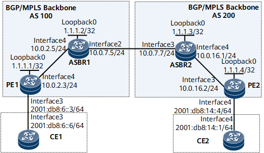
As shown in Figure 1, CE1 and CE2 belong to different VPNs. Communication between the VPNs spans two ASs: AS 100 and AS 200. VPN instances do not need to be created on each ASBR. Instead, each ASBR only needs to receive VPNv6 routes and transmit the routes to the peer ASBR. The MP-IBGP peer relationship needs to be established between each pair of PE and ASBR, and the MP-EBGP peer relationship needs to be established between the ASBRs.

Interfaces 1 through 4 in this example represent GE 0/1/1, GE 0/1/2, GE 0/1/3, and GE 0/1/4, respectively.
Device |
Interface |
IP Address |
|---|---|---|
CE1 |
GigabitEthernet0/1/0 |
2001:DB8:5::6/64 |
GigabitEthernet0/1/3 |
2001:DB8:6::6/64 |
|
PE1 |
LoopBack0 |
1.1.1.1/32 |
GigabitEthernet0/1/3 |
2001:DB8:6::3/24 |
|
GigabitEthernet0/1/4 |
10.0.2.3/24 |
|
ASBR1 |
LoopBack0 |
1.1.1.2/32 |
GigabitEthernet0/1/2 |
10.0.7.5/24 |
|
GigabitEthernet0/1/4 |
10.0.2.5/24 |
|
ASBR2 |
LoopBack0 |
1.1.1.3/32 |
GigabitEthernet0/1/3 |
10.0.7.7/24 |
|
GigabitEthernet0/1/4 |
10.0.16.1/24 |
|
PE2 |
Loopback1 |
1.1.1.4/32 |
GigabitEthernet0/1/3 |
10.0.16.2/24 |
|
GigabitEthernet0/1/4 |
2001:DB8:14::4/64 |
|
CE2 |
GigabitEthernet0/1/0 |
2001:DB8:3::1/64 |
GigabitEthernet0/1/4 |
2001:DB8:14::1/64 |
Precautions
When configuring inter-AS IPv6 NG MVPN Option B, note the following:
The MP-EBGP peer relationship needs to be established between ASBRs in different ASs. The MP-IBGP peer relationship needs to be established between the PE and ASBR in the same AS.
ASBRs do not filter received VPNv6 routes based on VPN targets.
Configuration Roadmap
The configuration roadmap is as follows:
Run an IGP in each AS to implement communication between nodes in the same AS. Establish an MPLS LDP LSP between the ASBR and PE in the same AS.
Configure the MP-EBGP peer relationship between ASBRs in different ASs. Configure the MP-IBGP peer relationship between the PE and ASBR in the same AS.
Configure a VPN instance on each PE and bind the interface that connects a PE to a CE to the VPN instance on that PE.
Enable MPLS on the ASBR interfaces connected to each other. Establish an MP-EBGP peer relationship between ASBRs and configure ASBRs not to filter VPNv6 routes based on VPN targets.
Configure a P2MP LSP to carry multicast traffic.
Configure PIM.
Data Preparation
To complete the configuration, you need the following data:
MPLS LSR IDs of the PEs and ASBRs (1.1.1.1, 1.1.1.2, 1.1.1.3, and 1.1.1.4)
Name (ngv6), RD (100:1 and 200:1), and export and import VPN targets (1:1) of the VPN instance on each PE
Procedure
- Configure an IGP on the MPLS backbone networks of AS100 and AS200, so that nodes on each MPLS backbone network can communicate with each other.
This example uses OSPF. For configuration details, see Configuration Files in this example.
- Configure IS-IS for communication between PEs and CEs. For configuration details, see Configuration Files in this example.
- Configure basic MPLS functions and MPLS LDP on the MPLS backbone networks of AS100 and AS200 to establish LDP LSPs.
# Configure PE1.
[~PE1] mpls lsr-id 1.1.1.1
[*PE1] mpls
[*PE1-mpls] quit
[*PE1] mpls ldp
[*PE1-mpls-ldp] quit
[*PE1] interface GigabitEthernet 0/1/4
[*PE1-GigabitEthernet0/1/4] mpls
[*PE1-GigabitEthernet0/1/4] mpls ldp
[*PE1-GigabitEthernet0/1/4] commit
[~PE1-GigabitEthernet0/1/4] quit
The procedure for configuring PE2 is similar to the procedure for configuring PE1. For configuration details, see Configuration Files in this example.
# Configure ASBR1.
[~ASBR1] mpls lsr-id 1.1.1.2
[*ASBR1] mpls
[*ASBR1-mpls] quit
[*ASBR1] mpls ldp
[*ASBR1-mpls-ldp] quit
[*ASBR1] interface GigabitEthernet 0/1/4
[*ASBR1-GigabitEthernet0/1/4] mpls
[*ASBR1-GigabitEthernet0/1/4] mpls ldp
[*ASBR1-GigabitEthernet0/1/4] commit
[~ASBR1-GigabitEthernet0/1/4] quit
The procedure for configuring ASBR2 is similar to the procedure for configuring ASBR1. For configuration details, see Configuration Files in this example.
After the configurations are complete, LDP peer relationships are set up between the PE and ASBR in each AS and between ASBRs. Run the display mpls ldp session command on each router. The command output shows that Session State is Operational. The following example uses the command output on PE1.
<PE1> display mpls ldp session
 LDP Session(s) in Public Network
 Codes: LAM(Label Advertisement Mode), SsnAge Unit(DDDD:HH:MM)
 An asterisk (*) before a session means the session is being deleted.
 -------------------------------------------------------------------------
 PeerID             Status      LAM  SsnRole  SsnAge      KASent/Rcv
 ------------------------------------------------------------------------
 1.1.1.2          Operational DU   Passive  0000:00:01  5/5
 -------------------------------------------------------------------------
 TOTAL: 1 session(s) Found.
- Configure an automatic mLDP P2MP LSP on PEs and ASBRs.
# Configure PE1.
[~PE1] mpls ldp
[~PE1-mpls-ldp] mldp p2mp
[*PE1-mpls-ldp] commit
[~PE1-mpls-ldp] quit
# Configure PE2.
[~PE2] mpls ldp
[~PE2-mpls-ldp] mldp p2mp
[*PE2-mpls-ldp] mldp recursive-fec
[*PE2-mpls-ldp] commit
[~PE2-mpls-ldp] quit
# Configure ASBR1.
[~ASBR1] mpls ldp
[~ASBR1-mpls-ldp] mldp p2mp
[*ASBR1-mpls-ldp] mldp recursive-fec
[*ASBR1-mpls-ldp] commit
[~ASBR1-mpls-ldp] quit
The procedure for configuring ASBR2 is similar to the procedure for configuring ASBR1. For configuration details, see Configuration Files in this example.
- Configure the MP-IBGP peer relationship between the PE and ASBR in the same AS.
# Configure PE1.
[~PE1] bgp 100
[*PE1-bgp] peer 1.1.1.2 as-number 100
[*PE1-bgp] peer 1.1.1.2 connect-interface loopback 0
[*PE1-bgp] ipv6-family vpnv6
[*PE1-bgp-af-vpnv6] peer 1.1.1.2 enable
[*PE1-bgp-af-vpnv6] commit
[~PE1-bgp-af-vpnv6] quit
[~PE1-bgp] quit
# Configure ASBR1.
[~ASBR1] bgp 100
[*ASBR1-bgp] peer 1.1.1.1 as-number 100
[*ASBR1-bgp] peer 1.1.1.1 connect-interface loopback 0
[*ASBR1-bgp] ipv6-family vpnv6
[*ASBR1-bgp-af-vpnv6] peer 1.1.1.1 enable
[*ASBR1-bgp-af-vpnv6] commit
[~ASBR1-bgp-af-vpnv6] quit
[~ASBR1-bgp] quit
The procedure for configuring AS200 is similar to the procedure for configuring AS100. For configuration details, see Configuration Files in this example.
After the configuration is complete, run the display bgp vpnv4 all peer command on the PE or ASBR. The command output shows that the MP-IBGP peer relationship between the PE and ASBR in the same AS or between ASBRs is in the Established state. The command output on PE1 is used as an example.
<PE1> display bgp vpnv6 all peer

 BGP local router ID : 1.1.1.9
 Local AS number : 100
 Total number of peers : 1         Peers in established state : 1

  Peer            V          AS  MsgRcvd  MsgSent  OutQ  Up/Down       State  PrefRcv

  1.1.1.2        4         100    18970    19008     0 91:51:24   Established    0
- Create VPN instances on PEs.
# Configure PE1.
[~PE1] ip vpn-instance ngv6
[*PE1-vpn-instance-ngv6] ipv6-family
[*PE1-vpn-instance-ngv6-af-ipv6] route-distinguisher 100:1
[*PE1-vpn-instance-ngv6-af-ipv6] vpn-target 1:1 both
[*PE1-vpn-instance-ngv6-af-ipv6] quit
[*PE1-vpn-instance-ngv6] quit
[*PE1] interface ethernet 0/1/3
[*PE1-GigabitEthernet0/1/3] ip binding vpn-instance ngv6
[*PE1-GigabitEthernet0/1/3] ipv6 enable
[*PE1-GigabitEthernet0/1/3] ip address 2001:db8:6::3 64
[*PE1-GigabitEthernet0/1/3] quit
[*PE1] commit
# Configure PE2.
[~PE2] ip vpn-instance ngv6
[*PE2-vpn-instance-ngv6] ipv6-family
[*PE2-vpn-instance-ngv6-af-ipv6] route-distinguisher 200:1
[*PE2-vpn-instance-ngv6-af-ipv6] vpn-target 1:1 both
[*PE2-vpn-instance-ngv6-af-ipv6] quit
[*PE2-vpn-instance-ngv6] quit
[*PE2] interface ethernet 0/1/4
[*PE2-GigabitEthernet0/1/4] ip binding vpn-instance ngv6
[*PE2-GigabitEthernet0/1/4] ipv6 enable
[*PE2-GigabitEthernet0/1/4] ip address 2001:db8:14::4 64
[*PE2-GigabitEthernet0/1/4] commit
[~PE2-GigabitEthernet0/1/4] quit
- Enable MPLS on the interfaces interconnecting ASBRs, establish the MP-EBGP relationship between ASBRs, and configure the ASBRs not to filter received VPNv6 routes based on VPN targets.
# Enable MPLS on GigabitEthernet0/1/2 connecting ASBR1 to ASBR2.
[~ASBR1] interface ethernet 0/1/2
[~ASBR1-GigabitEthernet0/1/2] ip address 10.0.7.5 24
[*ASBR1-GigabitEthernet0/1/2] mpls
[*ASBR1-GigabitEthernet0/1/2] mpls ldp
[*ASBR1-GigabitEthernet0/1/2] commit
[~ASBR1-GigabitEthernet0/1/2] quit
# Configure ASBR2: Enable MPLS on GigabitEthernet0/1/8 connecting to ASBR1.
[~ASBR2] interface ethernet 0/1/3
[~ASBR2-GigabitEthernet0/1/3] ip address 10.0.7.7 24
[*ASBR2-GigabitEthernet0/1/3] mpls
[*ASBR2-GigabitEthernet0/1/3] mpls ldp
[*ASBR2-GigabitEthernet0/1/3] commit
[~ASBR2-GigabitEthernet0/1/3] quit
# Configure ASBR1: Establish the MP-EBGP peer relationship with ASBR2 and configure ASBR1 not to filter received VPNv6 routes based on VPN targets.
[~ASBR1] bgp 100
[~ASBR1-bgp] peer 10.0.7.7 as-number 200
[*ASBR1-bgp] ipv6-family vpnv6
[*ASBR1-bgp-af-vpnv6] peer 10.0.7.7 enable
[*ASBR1-bgp-af-vpnv6] undo policy vpn-target
[*ASBR1-bgp-af-vpnv6] commit
[~ASBR1-bgp-af-vpnv6] quit
[~ASBR1-bgp] quit
# Configure ASBR2: Establish the MP-EBGP peer relationship with ASBR1 and configure ASBR2 not to filter received VPNv6 routes based on VPN targets.
[~ASBR2] bgp 200
[~ASBR2-bgp] peer 10.0.7.5 as-number 100
[*ASBR2-bgp] ipv6-family vpnv6
[*ASBR2-bgp-af-vpnv6] peer 10.0.7.5 enable
[*ASBR2-bgp-af-vpnv6] undo policy vpn-target
[*ASBR2-bgp-af-vpnv6] commit
[~ASBR2-bgp-af-vpnv6] quit
[~ASBR2-bgp] quit
After the configuration is complete, run the display bgp mvpn vpnv6 all peer command. The command output shows that the MP-EBGP peer relationship between ASBRs is in the Established state. The command output on ASBR1 is used as an example.
<ASBR1> display bgp mvpn vpnv6 all peer

 BGP local router ID : 1.1.1.2
 Local AS number : 100
 Total number of peers : 2         Peers in established state : 2

  Peer            V          AS  MsgRcvd  MsgSent  OutQ  Up/Down       State  PrefRcv

  1.1.1.1        4         100    17533    17554     0 127:24:5 Established    1
10.0.7.7        4         200    12343    34554     0 127:24:5 Established    1
- Configure BGP MVPN peers.
# Configure PE1.
[~PE1] bgp 100
[~PE1-bgp] ipv4-family unicast
[~PE1-bgp-af-ipv4] undo synchronization
[*PE1-bgp-af-ipv4] peer 1.1.1.2 enable
[*PE1-bgp-af-ipv4] commit
[~PE1-bgp-af-ipv4] quit
[~PE1-bgp] ipv6-family vpn-instance ngv6
[~PE1-bgp-af-vpn-ngv6] import-route isis 1
[*PE1-bgp-af-vpn-ngv6] commit
[~PE1-bgp-af-vpn-ngv6] quit
[~PE1-bgp] ipv6-family mvpn
[~PE1-bgp-af-mvpnv6] policy vpn-target
[*PE1-bgp-af-mvpnv6] peer 1.1.1.2 enable
[*PE1-bgp-af-mvpnv6] commit
[~PE1-bgp-af-mvpnv6] quit
[~PE1-bgp] quit
The configuration on PE2 is similar to the configuration on PE1. For configuration details, see Configuration Files in this example.
# Configure ASBR1.
[~ASBR1] bgp 100
[~ASBR1-bgp] ipv4-family unicast
[~ASBR1-bgp-af-ipv4] undo synchronization
[*ASBR1-bgp-af-ipv4] peer 10.0.7.7 enable
[*ASBR1-bgp-af-ipv4] peer 1.1.1.1 enable
[*ASBR1-bgp-af-ipv4] commit
[~ASBR1-bgp-af-ipv4] quit
[~ASBR1-bgp] ipv6-family mvpn
[~ASBR1-bgp-af-mvpnv6] undo policy vpn-target
[*ASBR1-bgp-af-mvpnv6] peer 10.0.7.7 enable
[*ASBR1-bgp-af-mvpnv6] peer 1.1.1.1 enable
[*ASBR1-bgp-af-mvpnv6] commit
[~ASBR1-bgp-af-mvpnv6] quit
[~ASBR1-bgp] quit
The procedure for configuring ASBR2 is similar to the procedure for configuring ASBR1. For configuration details, see Configuration Files in this example.
- Configure an mLDP LSP on PEs to carry multicast traffic.
# Configure PE1 as the sender PE.
[~PE1] multicast ipv6 mvpn 1.1.1.1
[~PE1] ip vpn-instance ngv6
[~PE1-vpn-instance-ngv6] ipv6-family
[~PE1-vpn-instance-ngv6-af-ipv6] multicast ipv6 routing-enable
[*PE1-vpn-instance-ngv6-af-ipv6] mvpn
[*PE1-vpn-instance-ngv6-af-ipv6-mvpn] sender-enable
[*PE1-vpn-instance-ngv6-af-ipv6-mvpn] c-multicast signaling bgp
[*PE1-vpn-instance-ngv6-af-ipv6-mvpn] rpt-spt mode
[*PE1-vpn-instance-ngv6-af-ipv6-mvpn] auto-discovery inter-as
[*PE1-vpn-instance-ngv6-af-ipv6-mvpn] ipmsi-tunnel
[*PE1-vpn-instance-ngv6-af-ipv6-mvpn-ipmsi] mldp
[*PE1-vpn-instance-ngv6-af-ipv6-mvpn-ipmsi] quit
[*PE1-vpn-instance-ngv6-af-ipv6-mvpn] quit
[*PE1-vpn-instance-ngv6-af-ipv6] quit
[*PE1-vpn-instance-ngv6] commit
[~PE1-vpn-instance-ngv6] quit
# Configure PE2 as the receiver PE.
[~PE2] multicast ipv6 mvpn 1.1.1.4
[~PE2] ip vpn-instance ngv6
[~PE2-vpn-instance-ngv6] ipv6-family
[~PE2-vpn-instance-ngv6-af-ipv6] multicast ipv6 routing-enable
[~PE2-vpn-instance-ngv6-af-ipv6] mvpn
[*PE2-vpn-instance-ngv6-af-ipv6-mvpn] c-multicast signaling bgp
[*PE2-vpn-instance-ngv6-af-ipv6-mvpn] rpt-spt mode
[*PE2-vpn-instance-ngv6-af-ipv6-mvpn] auto-discovery inter-as
[*PE2-vpn-instance-ngv6-af-ipv6-mvpn] ipmsi-tunnel
[*PE2-vpn-instance-ngv6-af-ipv6-mvpn-ipmsi] quit
[*PE2-vpn-instance-ngv6-af-ipv6-mvpn] quit
[*PE2-vpn-instance-ngv6-af-ipv6] quit
[*PE2-vpn-instance-ngv6] commit
[~PE2-vpn-instance-ngv6] quit
- Configure PIM.
# Configure CE1.
[~CE1] pim-ipv6
[~CE1-pim6] static-rp 2001:db8:6::3
[*CE1-pim6] commit
[~CE1-pim6] quit
[~CE1] multicast ipv6 routing-enable
[*CE1] interface GigabitEthernet 0/1/0
[*CE1-GigabitEthernet0/1/0] pim ipv6 sm
[*CE1-GigabitEthernet0/1/0] commit
[~CE1-GigabitEthernet0/1/0] quit
[~CE1] interface GigabitEthernet 0/1/3
[~CE1-GigabitEthernet0/1/3] pim ipv6 sm
[*CE1-GigabitEthernet0/1/3] commit
[~CE1-GigabitEthernet0/1/3] quit
# Configure CE2.
[~CE2] pim-ipv6
[~CE2-pim6] static-rp 2001:db8:6::3
[*CE2-pim6] commit
[~CE2-pim6] quit
[~CE2] multicast ipv6 routing-enable
[*CE2] interface GigabitEthernet 0/1/0
[*CE2-GigabitEthernet0/1/0] pim ipv6 sm
[*CE2-GigabitEthernet0/1/0] mld enable
[*CE2-GigabitEthernet0/1/1] mld static-group FF3E::1 source 2001:DB8:5::2
[*CE2-GigabitEthernet0/1/0] commit
[~CE2-GigabitEthernet0/1/0] quit
[~CE2] interface GigabitEthernet 0/1/4
[~CE2-GigabitEthernet0/1/4] pim ipv6 sm
[*CE2-GigabitEthernet0/1/4] commit
[~CE2-GigabitEthernet0/1/4] quit
# Configure PE1.
[~PE1] pim-ipv6 vpn-instance ngv6
[*PE1-pim6-ngv6] static-rp 2001:db8:6::3
[*PE1-pim6-ngv6] source-lifetime 60
[*PE1-pim6-ngv6] commit
[~PE1-pim6-ngv6] quit
[~PE1] interface GigabitEthernet 0/1/3
[~PE1-GigabitEthernet0/1/3] pim ipv6 sm
[*PE1-GigabitEthernet0/1/3] commit
[~PE1-GigabitEthernet0/1/3] quit
The configuration on PE2 is similar to the configuration on PE1. For configuration details, see Configuration Files in this example.
- Verify the configuration.
After the configurations are complete, CE1 and CE2 can successfully ping each other.
The following example uses the command output on CE1.
[~CE1] ping ipv6 2001:db8:14::1
  PING 2001:DB8:14::1: 56  data bytes, press CTRL_C to break
    Reply from 2001:DB8:14::1: bytes=56 Sequence=1 ttl=252 time=120 ms
    Reply from 2001:DB8:14::1: bytes=56 Sequence=2 ttl=252 time=73 ms
    Reply from 2001:DB8:14::1: bytes=56 Sequence=3 ttl=252 time=111 ms
    Reply from 2001:DB8:14::1: bytes=56 Sequence=4 ttl=252 time=86 ms
    Reply from 2001:DB8:14::1: bytes=56 Sequence=5 ttl=252 time=110 ms
  --- 2001:DB8:14::1 ping statistics ---
    5 packet(s) transmitted
    5 packet(s) received
    0.00% packet loss
    round-trip min/avg/max = 73/100/120 ms
Run the display pim ipv6 routing-table command on a PE to check the PIM routing table.
The following example uses the command output on PE1.
<PE1> display pim ipv6 vpn-instance ngv6 routing-table
 VPN-Instance: ngv6
 Total 1 (S, G) entry

 (2001:DB8:5::2, FF3E::1)
     Protocol: pim-ssm, Flag:
     UpTime: 00:24:09
     Upstream interface: through-BGP, Refresh time: 00:24:09
         Upstream neighbor: ::FFFF:1.1.1.2
         RPF prime neighbor: ::FFFF:1.1.1.2
     Downstream interface(s) information:
     Total number of downstreams: 1
        1: GigabitEthernet0/1/3
             Protocol: pim-ssm, UpTime: 00:24:09, Expires: 00:02:35
Configuration Files
CE1 configuration file
#
sysname CE1
#
multicast ipv6 routing-enable
#
isis 1
 is-level level-2
 ipv6 enable topology ipv6
 network-entity 10.0000.0000.0004.00
#
interface GigabitEthernet0/1/0
 undo shutdown
 ipv6 enable
 ipv6 address 2001:DB8:5::6 64
 isis ipv6 enable 1
 pim ipv6 sm
#
interface GigabitEthernet0/1/3
 undo shutdown
 ipv6 enable
 ipv6 address 2001:DB8:6::6 64
 isis ipv6 enable 1
 pim ipv6 sm
#
pim-ipv6
 static-rp 2001:DB8:6::3
#
return
PE1 configuration file
#
 sysname PE1
#
multicast ipv6 mvpn 1.1.1.1
#
ip vpn-instance ngv6
 ipv6-family
  route-distinguisher 100:1
  apply-label per-instance
  vpn-target 1:1 export-extcommunity
  vpn-target 1:1 import-extcommunity
  multicast ipv6 routing-enable
  mvpn
   sender-enable
   c-multicast signaling bgp
   rpt-spt mode
   auto-discovery inter-as
   ipmsi-tunnel
    mldp
#
mpls lsr-id 1.1.1.1
#
mpls
#
mpls ldp
 mldp p2mp
#
isis 1 vpn-instance ngv6
 is-level level-2
 network-entity 10.0000.0000.0006.00
 ipv6 enable topology ipv6
 ipv6 import-route bgp
#
interface GigabitEthernet0/1/3
 undo shutdown
 ip binding vpn-instance ngv6
 ipv6 enable
 ipv6 address 2001:DB8:6::3 64
 isis ipv6 enable 1
 pim ipv6 sm
#
interface GigabitEthernet0/1/4
 undo shutdown
 ip address 10.0.2.3 255.255.255.0
 mpls
 mpls ldp
#
interface LoopBack0
 ip address 1.1.1.1 255.255.255.255
#
bgp 100
 peer 1.1.1.2 as-number 100
 peer 1.1.1.2 connect-interface LoopBack0
 #
 ipv4-family unicast
  undo synchronization
  peer 1.1.1.2 enable
 #
 ipv6-family mvpn
  policy vpn-target
  peer 1.1.1.2 enable
 #
 ipv6-family vpnv6
  policy vpn-target
  peer 1.1.1.2 enable
 #
 ipv6-family vpn-instance ngv6
  import-route isis 1
#
ospf 1
 area 0.0.0.0
  network 10.0.2.0 0.0.0.255
  network 1.1.1.1 0.0.0.0
#
pim-ipv6 vpn-instance ngv6
 static-rp 2001:DB8:6::3
 source-lifetime 60
#
return
ASBR1 configuration file
#
 sysname ASBR1
#
mpls lsr-id 1.1.1.2
#
mpls
#
mpls ldp
 mldp p2mp
 mldp recursive-fec
#
interface GigabitEthernet0/1/2
 undo shutdown
 ip address 10.0.7.5 255.255.255.0
 mpls
 mpls ldp
#
interface GigabitEthernet0/1/4
 undo shutdown
 ip address 10.0.2.5 255.255.255.0
 mpls
 mpls ldp
#
interface LoopBack0
 ip address 1.1.1.2 255.255.255.255
#
bgp 100
 peer 10.0.7.7 as-number 200
 peer 1.1.1.1 as-number 100
 peer 1.1.1.1 connect-interface LoopBack0
 #
 ipv4-family unicast
 undo synchronization
  peer 10.0.7.7 enable
  peer 1.1.1.1 enable
 #
 ipv6-family mvpn
  undo policy vpn-target
  peer 10.0.7.7 enable
  peer 1.1.1.1 enable
 #
 ipv6-family vpnv6
  undo policy vpn-target
  peer 10.0.7.7 enable
  peer 1.1.1.1 enable
#
ospf 1
 area 0.0.0.0
  network 10.0.2.0 0.0.0.255
  network 1.1.1.2 0.0.0.0
#
ip route-static 1.1.1.3 255.255.255.255 10.0.7.7
#
return
ASBR2 configuration file
#
 sysname ASBR2
#
mpls lsr-id 1.1.1.3
#
mpls
#
mpls ldp
 mldp p2mp
 mldp recursive-fec
#
interface GigabitEthernet0/1/3
 undo shutdown
 ip address 10.0.7.7 255.255.255.0
 mpls
 mpls ldp
#
interface GigabitEthernet0/1/4
 undo shutdown
 ip address 10.0.16.1 255.255.255.0
 mpls
 mpls ldp
#
interface LoopBack0
 ip address 1.1.1.3 255.255.255.255
#
bgp 200
 peer 10.0.7.5 as-number 100
 peer 1.1.1.4 as-number 200
 peer 1.1.1.4 connect-interface LoopBack0
 #
 ipv4-family unicast
  undo synchronization
  peer 10.0.7.5 enable
  peer 1.1.1.4 enable
 #
 ipv6-family mvpn
undo policy vpn-target
  peer 10.0.7.5 enable
  peer 1.1.1.4 enable
 #
 ipv6-family vpnv6
  undo policy vpn-target
  peer 10.0.7.5 enable
  peer 1.1.1.4 enable
#
ospf 1
 area 0.0.0.0
  network 10.0.16.0 0.0.0.255
  network 1.1.1.3 0.0.0.0
#
ip route-static 1.1.1.2 255.255.255.255 10.0.7.5
#
return
PE2 configuration file
#
sysname PE2
#
multicast ipv6 mvpn 1.1.1.4
#
ip vpn-instance ngv6v6
 #
 ipv6-family
  route-distinguisher 200:1
  apply-label per-instance
  vpn-target 1:1 export-extcommunity
  vpn-target 1:1 import-extcommunity
  multicast ipv6 routing-enable
  mvpn
   c-multicast signaling bgp
   rpt-spt mode
   auto-discovery inter-as
#
mpls lsr-id 1.1.1.4
#
mpls
#
mpls ldp
 mldp p2mp
 mldp recursive-fec
#
isis 1 vpn-instance ngv6
 is-level level-2
 network-entity 10.0000.0000.0007.00
 ipv6 enable topology ipv6
 ipv6 import-route bgp
#
interface GigabitEthernet0/1/3
 undo shutdown
 ip address 10.0.16.2 255.255.255.0
 mpls
 mpls ldp
#
interface GigabitEthernet0/1/4
 undo shutdown
 ip binding vpn-instance ngv6
 ipv6 enable
 ipv6 address 2001:DB8:14::4 64
 isis ipv6 enable 1
 pim ipv6 sm
#
interface LoopBack0
 ip address 1.1.1.4 255.255.255.255
#
bgp 200
 peer 1.1.1.3 as-number 200
 peer 1.1.1.3 connect-interface LoopBack0
#
 ipv4-family unicast
  undo synchronization
  peer 1.1.1.3 enable
#
 ipv6-family mvpn
  policy vpn-target
  peer 1.1.1.3 enable
#
 ipv6-family vpnv6
  policy vpn-target
  peer 1.1.1.3 enable
#
 ipv6-family vpn-instance ngv6
  import-route isis 1
#
ospf 1
 area 0.0.0.0
  network 10.0.16.0 0.0.0.255
  network 1.1.1.4 0.0.0.0
#
pim-ipv6 vpn-instance ngv6
 static-rp 2001:DB8:6::3
 source-lifetime 60
#
return
CE2 configuration file
#
sysname CE2
#
multicast ipv6 routing-enable
#
interface GigabitEthernet0/1/0
 undo shutdown
 ipv6 enable
 ipv6 address 2001:DB8:3::1 64
 isis ipv6 enable 1
 pim ipv6 sm
 mld enable
 mld static-group FF3E::1 source 2001:DB8:5::2
#
interface GigabitEthernet0/1/4
 undo shutdown
 ipv6 enable
 ipv6 address 2001:DB8:14::1 64
 isis ipv6 enable 1
 pim ipv6 sm
#
isis 1
 is-level level-2
 ipv6 enable topology ipv6
 network-entity 10.0000.0000.0004.00
#
pim-ipv6
 static-rp 2001:DB8:6::3
#
return