Example for Configuring VPLS-based CFM
This section provides an example for configuring virtual private LAN service (VPLS)-based connectivity fault management (CFM).
Networking Requirements
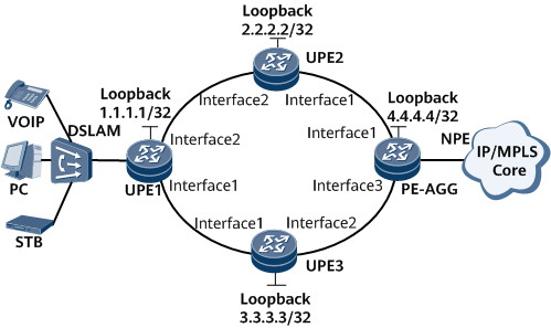
As shown in Figure 1, the UPEs are connected to the PE-AGG over a VPLS network. Configure VPLS-based CFM to detect link faults on the network.

Interfaces 1 through 3 in this example are GE 0/1/0, GE 0/1/1, GE 0/1/2 respectively.
Device |
Interface |
IP Address |
|---|---|---|
UPE1 |
Loopback |
1.1.1.1/32 |
Interface1 |
192.168.3.1/24 |
|
Interface2 |
192.168.1.1/24 |
|
UPE2 |
Loopback |
2.2.2.2/32 |
Interface1 |
192.168.2.1/24 |
|
Interface2 |
192.168.1.2/24 |
|
UPE3 |
Loopback |
3.3.3.3/32 |
Interface1 |
192.168.3.2/24 |
|
Interface2 |
192.168.4.1/24 |
|
PE-AGG |
Loopback |
4.4.4.4/32 |
Interface1 |
192.168.2.2/24 |
|
Interface3 |
192.168.4.2/24 |
Configuration Roadmap
The configuration roadmap is as follows:
Assign an IP address to each interface.
Configure an Interior Gateway Protocol (IGP) on the backbone network and enable basic Multiprotocol Label Switching (MPLS) functions.
Create a virtual switching instance (VSI) bind it to an attachment circuit (AC) interface.
Configure VPLS-based CFM.
Data Preparation
To complete the configuration, you need the following data:
Interface IP addresses
Label switching router (LSR) IDs used for basic MPLS functions
VSI name and ID
Maintenance domain (MD) name, maintenance association (MA) name, maintenance association end point (MEP) ID and type, and name of the interface on which the MEP resides
Procedure
- Assign an IP address to each interface.
# Configure UPE1.
<HUAWEI> system-view
[~HUAWEI] sysname UPE1
[*HUAWEI] commit
[~UPE1] interface loopback 0
[*UPE1-LoopBack0] ip address 1.1.1.1 32
[*UPE1-LoopBack0] quit
[*UPE1] interface gigabitethernet 0/1/1
[*UPE1-Gigabitethernet0/1/1] ip address 192.168.1.1 24
[*UPE1-Gigabitethernet0/1/1] undo shutdown
[*UPE1-Gigabitethernet0/1/1] quit
[*UPE1] interface gigabitethernet 0/1/0
[*UPE1-Gigabitethernet0/1/0] ip address 192.168.3.1 24
[*UPE1-Gigabitethernet0/1/0] undo shutdown
[*UPE1-Gigabitethernet0/1/0] quit
[*UPE1-Gigabitethernet0/1/0] commit
# Configure UPE2.
<HUAWEI> system-view
[~HUAWEI] sysname UPE2
[*HUAWEI] commit
[~UPE2] interface LoopBack0
[*UPE2-LoopBack0] ip address 2.2.2.2 32
[*UPE2-LoopBack0] quit
[*UPE2] interface gigabitethernet 0/1/1
[*UPE2-Gigabitethernet0/1/1] ip address 192.168.1.2 24
[*UPE2-Gigabitethernet0/1/1] undo shutdown
[*UPE2-Gigabitethernet0/1/1] quit
[*UPE2] interface gigabitethernet 0/1/0
[*UPE2-Gigabitethernet0/1/0] ip address 192.168.2.1 24
[*UPE2-Gigabitethernet0/1/0] undo shutdown
[*UPE2-Gigabitethernet0/1/0] quit
[*UPE2-Gigabitethernet0/1/0] commit
# Configure UPE3.
<HUAWEI> system-view
[~HUAWEI] sysname UPE3
[*HUAWEI] commit
[~UPE3] interface loopback 0
[*UPE3-LoopBack0] ip address 3.3.3.3 32
[*UPE3-LoopBack0] quit
[*UPE3] interface gigabitethernet 0/1/0
[*UPE3-Gigabitethernet0/1/0] ip address 192.168.3.2 24
[*UPE3-Gigabitethernet0/1/0] undo shutdown
[*UPE3-Gigabitethernet0/1/0] quit
[*UPE3] interface gigabitethernet 0/1/1
[*UPE3-Gigabitethernet0/1/1] ip address 192.168.4.1 24
[*UPE3-Gigabitethernet0/1/1] undo shutdown
[*UPE3-Gigabitethernet0/1/1] quit
[*UPE3-Gigabitethernet0/1/1] commit
# Configure the PE-AGG.
<HUAWEI> system-view
[~HUAWEI] sysname PEAGG
[*HUAWEI] commit
[~PEAGG] interface loopback 0
[*PEAGG-LoopBack0] ip address 4.4.4.4 32
[*PEAGG-LoopBack0] quit
[*PEAGG] interface gigabitethernet 0/1/0
[*PEAGG-Gigabitethernet0/1/0] ip address 192.168.2.2 24
[*PEAGG-Gigabitethernet0/1/0] undo shutdown
[*PEAGG-Gigabitethernet0/1/0] quit
[*PEAGG] interface gigabitethernet 0/1/2
[*PEAGG-Gigabitethernet0/1/2] ip address 192.168.4.2 24
[*PEAGG-Gigabitethernet0/1/2] undo shutdown
[*PEAGG-Gigabitethernet0/1/2] quit
[*PEAGG-Gigabitethernet0/1/2] commit
- Configure an IGP on the backbone network. This example uses Open Shortest Path First (OSPF).
# Configure UPE1.
[~UPE1] ospf 1
[*UPE1-ospf-1] area 0
[*UPE1-ospf-1-area-0.0.0.0] network 1.1.1.1 0.0.0.0
[*UPE1-ospf-1-area-0.0.0.0] network 192.168.1.0 0.0.0.255
[*UPE1-ospf-1-area-0.0.0.0] network 192.168.3.0 0.0.0.255
[*UPE1-ospf-1-area-0.0.0.0] quit
[*UPE1-ospf-1] quit
[*UPE1] commit
# Configure UPE2.
[~UPE2] ospf 1
[*UPE2-ospf-1] area 0
[*UPE2-ospf-1-area-0.0.0.0] network 2.2.2.2 0.0.0.0
[*UPE2-ospf-1-area-0.0.0.0] network 192.168.1.0 0.0.0.255
[*UPE2-ospf-1-area-0.0.0.0] network 192.168.2.0 0.0.0.255
[*UPE2-ospf-1-area-0.0.0.0] quit
[*UPE2-ospf-1] quit
[*UPE2] commit
# Configure UPE3.
[~UPE3] ospf 1
[*UPE3-ospf-1] area 0
[*UPE3-ospf-1-area-0.0.0.0] network 3.3.3.3 0.0.0.0
[*UPE3-ospf-1-area-0.0.0.0] network 192.168.3.0 0.0.0.255
[*UPE3-ospf-1-area-0.0.0.0] network 192.168.4.0 0.0.0.255
[*UPE3-ospf-1-area-0.0.0.0] quit
[*UPE3-ospf-1] quit
[*UPE3] commit
# Configure the PE-AGG.
[~PEAGG] ospf 1
[*PEAGG-ospf-1] area 0
[*PEAGG-ospf-1-area-0.0.0.0] network 4.4.4.4 0.0.0.0
[*PEAGG-ospf-1-area-0.0.0.0] network 192.168.2.0 0.0.0.255
[*PEAGG-ospf-1-area-0.0.0.0] network 192.168.4.0 0.0.0.255
[*PEAGG-ospf-1-area-0.0.0.0] quit
[*PEAGG-ospf-1] quit
[*PEAGG] commit
After the configuration is complete, run the display ip routing-table command. The command output shows that an OSPF route exists between Loopback0 interfaces of each UPE and the PE-AGG.
The following example uses the command output on UPE1.
[*UPE1] display ip routing-table
Route Flags: R - relay, D - download to fib, T - to vpn-instance, B - black hole route                                      ------------------------------------------------------------------------------
Routing Table: Public
         Destinations : 26       Routes : 27
                                                                                 Destination/Mask    Proto   Pre  Cost      Flags NextHop         Interface
                                                                                         1.1.1.1/32  Direct  0    0           D   127.0.0.1       LoopBack0
        2.2.2.2/32  OSPF    10   1           D   192.168.1.2     GigabitEthernet
0/1/1                                                                                    3.3.3.3/32  OSPF    10   1           D   192.168.3.2     GigabitEthernet
0/1/0                                                                                    4.4.4.4/32  OSPF    10   2           D   192.168.1.2     GigabitEthernet
0/1/1                                                                                                OSPF    10   2           D   192.168.3.2     GigabitEthernet
0/1/0                                                                                  127.0.0.0/8   Direct  0    0           D   127.0.0.1       InLoopBack0
      127.0.0.1/32  Direct  0    0           D   127.0.0.1       InLoopBack0
127.255.255.255/32  Direct  0    0           D   127.0.0.1       InLoopBack0
    192.168.1.0/24  Direct  0    0           D   192.168.1.1     GigabitEthernet
0/1/1                                                                                192.168.1.1/32  Direct  0    0           D   127.0.0.1       GigabitEthernet
0/1/1                                                                              192.168.1.255/32  Direct  0    0           D   127.0.0.1       GigabitEthernet
0/1/1                                                                                192.168.2.0/24  OSPF    10   2           D   192.168.1.2     GigabitEthernet
0/1/1                                                                                192.168.3.0/24  Direct  0    0           D   192.168.3.1     GigabitEthernet
0/1/0                                                                                192.168.3.1/32  Direct  0    0           D   127.0.0.1       GigabitEthernet
0/1/0                                                                              192.168.3.255/32  Direct  0    0           D   127.0.0.1       GigabitEthernet
0/1/0                                                                                192.168.4.0/24  OSPF    10   2           D   192.168.3.2     GigabitEthernet
0/1/0                                                                                255.255.255.255/32  Direct  0    0           D   127.0.0.1       InLoopBack0
- Enable basic MPLS functions and LDP on the backbone network.
# Configure UPE1.
[~UPE1] mpls lsr-id 1.1.1.1
[*UPE1] mpls
[*UPE1-mpls] quit
[*UPE1] mpls ldp
[*UPE1-mpls-ldp] quit
[*UPE1] mpls l2vpn
[*UPE1-l2vpn] quit
[*UPE1] interface gigabitethernet 0/1/1
[*UPE1-Gigabitethernet0/1/1] mpls
[*UPE1-Gigabitethernet0/1/1] mpls ldp
[*UPE1-Gigabitethernet0/1/1] quit
[*UPE1] interface gigabitethernet 0/1/0
[*UPE1-Gigabitethernet0/1/0] mpls
[*UPE1-Gigabitethernet0/1/0] mpls ldp
[*UPE1-Gigabitethernet0/1/0] quit
[*UPE1] commit
# Configure UPE2.
[~UPE2] mpls lsr-id 2.2.2.2
[*UPE2] mpls
[*UPE2-mpls] quit
[*UPE2] mpls ldp
[*UPE2-mpls-ldp] quit
[*UPE2] mpls l2vpn
[*UPE2-l2vpn] quit
[*UPE2] interface gigabitethernet0/1/1
[*UPE2-Gigabitethernet0/1/1] mpls
[*UPE2-Gigabitethernet0/1/1] mpls ldp
[*UPE2-Gigabitethernet0/1/1] quit
[*UPE2] interface gigabitethernet0/1/0
[*UPE2-Gigabitethernet0/1/0] mpls
[*UPE2-Gigabitethernet0/1/0] mpls ldp
[*UPE2-Gigabitethernet0/1/0] quit
[*UPE2] commit
# Configure UPE3.
[~UPE3] mpls lsr-id 3.3.3.3
[*UPE3] mpls
[*UPE3-mpls] quit
[*UPE3] mpls ldp
[*UPE3-mpls-ldp] quit
[*UPE3] mpls l2vpn
[*UPE3-l2vpn] quit
[*UPE3] interface gigabitethernet 0/1/0
[*UPE3-Gigabitethernet0/1/0] mpls
[*UPE3-Gigabitethernet0/1/0] mpls ldp
[*UPE3-Gigabitethernet0/1/0] quit
[*UPE3] interface gigabitethernet 0/1/1
[*UPE3-Gigabitethernet0/1/1] mpls
[*UPE3-Gigabitethernet0/1/1] mpls ldp
[*UPE3-Gigabitethernet0/1/1] quit
[*UPE3] commit
# Configure the PE-AGG.
[~PEAGG] mpls lsr-id 4.4.4.4
[*PEAGG] mpls
[*PEAGG-mpls] quit
[*PEAGG] mpls ldp
[*PEAGG-mpls-ldp] quit
[*PEAGG] mpls l2vpn
[*PEAGG-l2vpn] quit
[*PEAGG] interface gigabitethernet 0/1/0
[*PEAGG-Gigabitethernet0/1/0] mpls
[*EAGG-Gigabitethernet0/1/0] mpls ldp
[*PEAGG-Gigabitethernet0/1/0] quit
[*PEAGG] interface gigabitethernet 0/1/2
[*PEAGG-Gigabitethernet0/1/2] mpls
[*PEAGG-Gigabitethernet0/1/2] mpls ldp
[*PEAGG-Gigabitethernet0/1/2] quit
[*PEAGG] commit
After the configuration is complete, run the display mpls ldp session command. The command output shows that Label Distribution Protocol (LDP) sessions have been established between each UPE and the PE-AGG.
The following example uses the command output on UPE1.
[~UPE1] display mpls ldp session
 LDP Session(s) in Public Network
 Codes: LAM(Label Advertisement Mode), SsnAge Unit(DDDD:HH:MM)
 Codes: LAM(Label Advertisement Mode), SsnAge Unit(DDDD:HH:MM)
 An asterisk (*) before a session means the session is being deleted.
 ------------------------------------------------------------------------------
 PeerID             Status      LAM  SsnRole  SsnAge      KASent/Rcv
 ------------------------------------------------------------------------------
 2.2.2.2:0          Operational DU   Passive  0000:00:46  187/187
 3.3.3.3:0          Operational DU   Passive  0000:00:44  177/177
 ------------------------------------------------------------------------------
 TOTAL: 2 session(s) Found.
- Create a VSI and specify LDP as its signaling protocol.
# Configure UPE1.
[~UPE1] vsi ldp1 static
[*UPE1-vsi-ldp1] pwsignal ldp
[*UPE1-vsi-ldp1-ldp] vsi-id 2
[*UPE1-vsi-ldp1-ldp] peer 2.2.2.2
[*UPE1-vsi-ldp1-ldp] peer 3.3.3.3
[*UPE1-vsi-ldp1-ldp] quit
[*UPE1-vsi-ldp1] quit
[*UPE1] commit
# Configure UPE2.
[~UPE2] vsi ldp1 static
[*UPE2-vsi-ldp1] pwsignal ldp
[*UPE2-vsi-ldp1-ldp] vsi-id 2
[*UPE2-vsi-ldp1-ldp] peer 1.1.1.1
[*UPE2-vsi-ldp1-ldp] peer 4.4.4.4
[*UPE2-vsi-ldp1-ldp] commit
# Configure UPE3.
[~UPE3] vsi ldp1 static
[*UPE3-vsi-ldp1] pwsignal ldp
[*UPE3-vsi-ldp1-ldp] vsi-id 2
[*UPE3-vsi-ldp1-ldp] peer 1.1.1.1
[*UPE3-vsi-ldp1-ldp] peer 4.4.4.4
[*UPE3-vsi-ldp1-ldp] commit
# Configure the PE-AGG.
[~PEAGG] vsi ldp1 static
[*PEAGG-vsi-ldp1] pwsignal ldp
[*PEAGG-vsi-ldp1-ldp] vsi-id 2
[*PEAGG-vsi-ldp1-ldp] peer 3.3.3.3
[*PEAGG-vsi-ldp1-ldp] peer 2.2.2.2
[*PEAGG-vsi-ldp1-ldp] commit
- Bind the VSI to an AC interface.
# Configure UPE1.
[~UPE1] interface gigabitethernet 0/1/2.1
[*UPE1-GigabitEthernet0/1/2.1] vlan-type dot1q 2
[*UPE1-GigabitEthernet0/1/2.1] l2 binding vsi ldp1
[*UPE1-GigabitEthernet0/1/2.1] undo shutdown
[*UPE1-GigabitEthernet0/1/2.1] quit
[*UPE1] commit
# Configure the PE-AGG.
[~PEAGG] interface gigabitethernet 0/1/1.1
[*PEAGG-GigabitEthernet0/1/1.1] vlan-type dot1q 2
[*PEAGG-GigabitEthernet0/1/1.1] l2 binding vsi ldp1
[*PEAGG-GigabitEthernet0/1/1.1] undo shutdown
[*PEAGG-GigabitEthernet0/1/1.1] quit
[*PEAGG] commit
After the configuration is complete, run the display vsi name ldp1 verbose command to view detailed information about the VSI named ldp1.
The following example uses the command output on UPE1.
[~UPE1] display vsi name ldp1 verbose
                                                                                 ***VSI Name               : ldp1
    Administrator VSI      : no
    Isolate Spoken         : disable
    VSI Index              : 0
    PW Signaling           : ldp
    Member Discovery Style : static
    Bridge-domain Mode     : disable
    PW MAC Learn Style     : unqualify
    Encapsulation Type     : vlan
    MTU                    : 1500
    Diffserv Mode          : uniform
    Service Class          : --
    Color                  : --
    DomainId               : 255
    Domain Name            :
    Ignore AcState         : disable
    P2P VSI                : disable
    Create Time            : 0 days, 0 hours, 38 minutes, 30 seconds
    VSI State              : up
    Resource Status        : Valid
                                                                                     VSI ID                 : 1
   *Peer Router ID         : 2.2.2.2
    primary or secondary   : primary
    ignore-standby-state   : no
    VC Label               : 4099
    Peer Type              : dynamic
    Session                : up
    Tunnel ID              : 0x41004000
    Broadcast Tunnel ID    : 0x41004000
    Broad BackupTunnel ID  : 0x0
    CKey                   : 2
    NKey                   : 1
    Stp Enable             : 0
    PwIndex                : 0
    Control Word           : enable
   *Peer Router ID         : 3.3.3.3
    primary or secondary   : primary
    ignore-standby-state   : no
    VC Label               : 4100
    Peer Type              : dynamic
    Session                : up
    Tunnel ID              : 0x41004001
    Broadcast Tunnel ID    : 0x41004001
    Broad BackupTunnel ID  : 0x0
    CKey                   : 4
    NKey                   : 3
    Stp Enable             : 0
    PwIndex                : 0
    Control Word           : enable
                                                                                     Interface Name         : GigabitEthernet0/1/2.1
    State                  : up
    Access Port            : false
    Last Up Time           : 2012/04/26 15:47:02
    Total Up Time          : 0 days, 0 hours, 15 minutes, 38 seconds
                                                                                   **PW Information:
                                                                                    *Peer Ip Address        : 2.2.2.2
    PW State               : up
    Local VC Label         : 4099
    Remote VC Label        : 4099
    Remote Control Word    : enable
    PW Type                : label
    Tunnel ID              : 0x41004000
    Broadcast Tunnel ID    : 0x41004000
    Broad BackupTunnel ID  : 0x0
    Ckey                   : 0x2
    Nkey                   : 0x1
    Main PW Token          : 0x41004000
    Slave PW Token         : 0x0
    Tnl Type               : LSP
    OutInterface           : GigabitEthernet0/1/1
    Backup OutInterface    :
    Stp Enable             : 0
    Mac Flapping           : 0
    PW Last Up Time        : 2012/04/26 15:47:02
    PW Total Up Time       : 0 days, 0 hours, 15 minutes, 9 seconds
   *Peer Ip Address        : 3.3.3.3
    PW State               : up
    Local VC Label         : 4100
    Remote VC Label        : 4099
    Remote Control Word    : enable
    PW Type                : label
    Tunnel ID              : 0x41004001
    Broadcast Tunnel ID    : 0x41004001
    Broad BackupTunnel ID  : 0x0
    Ckey                   : 0x4
    Nkey                   : 0x3
    Main PW Token          : 0x41004001
    Slave PW Token         : 0x0
    Tnl Type               : LSP
    OutInterface           : GigabitEthernet0/1/0
    Backup OutInterface    :
    Stp Enable             : 0
    Mac Flapping           : 0
    PW Last Up Time        : 2012/04/26 15:47:10
    PW Total Up Time       : 0 days, 0 hours, 6 minutes, 37 seconds
- Configure VPLS-based CFM on UPE1 and the PE-AGG.
# Configure UPE1.
[~UPE1] cfm enable
[*UPE1] cfm md md1
[*UPE1-md-md1] ma ma1
[*UPE1-md-md1-ma-ma1] ccm-interval 100
[*UPE1-md-md1-ma-ma1] map vsi ldp1
[*UPE1-md-md1-ma-ma1] mep mep-id 1 interface gigabitethernet 0/1/2.1 inward
[*UPE1-md-md1-ma-ma1] remote-mep mep-id 2
[*UPE1-md-md1-ma-ma1] mep ccm-send enable
[*UPE1-md-md1-ma-ma1] remote-mep ccm-receive enable
[*UPE1-md-md1-ma-ma1] quit
[*UPE1-md-md1] commit
# Configure the PE-AGG.
[~PEAGG] cfm enable
[*PEAGG] cfm md md1
[*PEAGG-md-md1] ma ma1
[*PEAGG-md-md1-ma-ma1] ccm-interval 100
[*PEAGG-md-md1-ma-ma1] map vsi ldp1
[*PEAGG-md-md1-ma-ma1] mep mep-id 2 interface gigabitethernet 0/1/1.1 inward
[*PEAGG-md-md1-ma-ma1] remote-mep mep-id 1
[*PEAGG-md-md1-ma-ma1] mep ccm-send enable
[*PEAGG-md-md1-ma-ma1] remote-mep ccm-receive enable
[*PEAGG-md-md1-ma-ma1] quit
[*PEAGG-md-md1] commit
- Verify the configuration.
After completing the configurations, run the display cfm mep and display cfm remote-mep commands on UPE1 or the PE-AGG. The command output shows that VPLS-based CFM has been established.
The following example uses the command output on UPE1.
[~UPE1] display cfm mep md md1
The total number of MEPs is : 1
--------------------------------------------------
 MD Name            : md1
 MD Name Format     : string
 Level              : 0
 MA Name            : ma1
 MEP ID             : 1
 VLAN ID            : --
 VSI Name           : ldp1
 L2VC ID            : --
 L2VPN Name         : --  CE ID              : --  CE Offset          : --
  L2TPV3 Tunnel Name            : --
 L2TPV3 Local Connection Name  : --
 Interface Name     : GigabitEthernet0/1/2.1
 CCM Send           : enabled
 Direction          : inward
 MAC Address        : 00e0-fc12-7880
 MEP Pe-vid         : --
 MEP Ce-vid         : --
 MEP Vid            : --
 Alarm Status       : none
 Alarm RDI          : enabled  Bandwidth Receive  : false  Bandwidth          : --
[~UPE1] display cfm remote-mep
The total number of RMEPs is : 1
The status of RMEPs : 1 up, 0 down, 0 disable
--------------------------------------------------
 MD Name            : md1
 Level              : 0
 MA Name            : ma1
 RMEP ID            : 2
 VLAN ID            : --
 VSI Name           : ldp1
 L2VC ID            : --
 L2VPN Name         : --  CE ID              : --  CE Offset          : --
  L2TPV3 Tunnel Name            : --
 L2TPV3 Local Connection Name  : --
  CCM Send           : enabled
 MAC                : 00e0-fc12-7890
 Trigger-If-Down    : disabled
 CFM Status         : up
 Alarm Status       : none
 Interface TLV      : --
 Port Status TLV    : --
Configuration Files
UPE1 configuration file
#
sysname UPE1
#
vlan batch 2
#
cfm version standard
cfm enable
#
mpls lsr-id 1.1.1.1
mpls
#
mpls l2vpn
#
vsi ldp1 static
 pwsignal ldp
  vsi-id 1
  peer 2.2.2.2
  peer 3.3.3.3
#
mpls ldp
#
interface GigabitEthernet0/1/0
 undo shutdown
 ip address 192.168.3.1 255.255.255.0
 mpls
 mpls ldp
#
interface GigabitEthernet0/1/1
 undo shutdown
 ip address 192.168.1.1 255.255.255.0
 mpls
 mpls ldp
#
interface GigabitEthernet0/1/2
 undo shutdown
#
interface GigabitEthernet0/1/2.1
 vlan-type dot1q 2
 l2 binding vsi ldp1
#
interface LoopBack0
 ip address 1.1.1.1 255.255.255.255
#
ospf 1
 area 0.0.0.0
  network 1.1.1.1 0.0.0.0
  network 192.168.1.0 0.0.0.255
  network 192.168.3.0 0.0.0.255
#
cfm md md1
 ma ma1
  map vsi ldp1
  ccm-interval 100
  mep mep-id 1 interface GigabitEthernet0/1/2.1 inward
  mep ccm-send enable
  remote-mep mep-id 2
  remote-mep ccm-receive enable
#
return
UPE2 configuration file
#
sysname UPE2
#
cfm version standard
cfm enable
#
mpls lsr-id 2.2.2.2
mpls
#
mpls l2vpn
#
vsi ldp1 static
 pwsignal ldp
  vsi-id 1
  peer 1.1.1.1
  peer 4.4.4.4
#
mpls ldp
#
interface GigabitEthernet0/1/0
 undo shutdown
 ip address 192.168.2.1 255.255.255.0
 mpls
 mpls ldp
#
interface GigabitEthernet0/1/1
 undo shutdown
 ip address 192.168.1.2 255.255.255.0
 mpls
 mpls ldp
#
interface LoopBack0
 ip address 2.2.2.2 255.255.255.255
#
ospf 1
 area 0.0.0.0
  network 2.2.2.2 0.0.0.0
  network 192.168.1.0 0.0.0.255
  network 192.168.2.0 0.0.0.255
#
return
UPE3 configuration file
#
sysname UPE3
#
mpls lsr-id 3.3.3.3
mpls
#
mpls l2vpn
#
vsi ldp1 static
 pwsignal ldp
  vsi-id 1
  peer 1.1.1.1
  peer 4.4.4.4
#
mpls ldp
#
interface GigabitEthernet0/1/0
 undo shutdown
 ip address 192.168.3.2 255.255.255.0
 mpls
 mpls ldp
#
interface GigabitEthernet0/1/1
 undo shutdown
 ip address 192.168.4.1 255.255.255.0
 mpls
 mpls ldp
#
interface LoopBack0
 ip address 3.3.3.3 255.255.255.255
#
ospf 1
 area 0.0.0.0
  network 1.1.1.1 0.0.0.0
  network 3.3.3.3 0.0.0.0
  network 192.168.3.0 0.0.0.255
  network 192.168.4.0 0.0.0.255
#
return
PE-AGG configuration file
#
sysname PEAGG
#
cfm version standard
cfm enable
#
mpls lsr-id 4.4.4.4
mpls
#
mpls l2vpn
#
vsi ldp1 static
 pwsignal ldp
  vsi-id 1
  peer 2.2.2.2
  peer 3.3.3.3
#
mpls ldp
#
interface GigabitEthernet0/1/0
 undo shutdown
 ip address 192.168.2.2 255.255.255.0
 mpls
 mpls ldp
#
interface GigabitEthernet0/1/2
 undo shutdown
 ip address 192.168.4.2 255.255.255.0
 mpls
 mpls ldp
#
interface GigabitEthernet0/1/1
 undo shutdown
#
interface GigabitEthernet0/1/1.1
 vlan-type dot1q 2
 l2 binding vsi ldp1
#
interface LoopBack0
 ip address 4.4.4.4 255.255.255.255
#
ospf 1
 area 0.0.0.0
  network 4.4.4.4 0.0.0.0
  network 192.168.2.0 0.0.0.255
  network 192.168.4.0 0.0.0.255
#
interface LoopBack0
 ip address 4.4.4.4 255.255.255.255
#
ospf 1
 area 0.0.0.0
  network 4.4.4.4 0.0.0.0
  network 192.168.2.0 0.0.0.255
  network 192.168.4.0 0.0.0.255
#
cfm md md1
 ma ma1
  map vsi ldp1
  ccm-interval 100
  mep mep-id 2 interface GigabitEthernet0/1/1.1 inward
  mep ccm-send enable
  remote-mep mep-id 1
  remote-mep ccm-receive enable
#
return