Example for Configuring Basic Ethernet CFM Functions Based on BGP VPWS
Configure a BGP VLL on two PEs, and configure CFM on the two PEs' access interfaces. The BGP VLL can use CFM to monitor VC connectivity.
Context
Networking Requirements
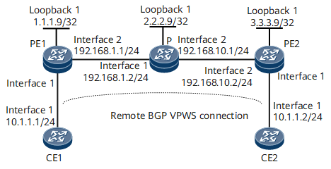
On the network shown in Figure 1, CE1 and CE2 connect to different PEs. A remote BGP VPWS connection needs to be established between PE1 and PE2 for the two CEs to communicate. Configure a BGP VLL on PE1 and PE2. The VLL is Up. Configure CFM on the access interfaces of PE1 and PE2. The remote MEP is Up. If the VC in the VLL fails, the remote MEP goes Down.

Configuration Roadmap
The configuration roadmap is as follows:
Configure a routing protocol on the PEs and P of the backbone network to ensure IP connectivity and configure basic MPLS functions and LDP.
Configure PEs to exchange VPWS information as BGP peers.
Enable MPLS L2VPN on PEs and create a remote BGP VPWS connection from CE1 and CE2.
Associate an MA with a VPWS on PE1 and PE2.
Establish a remote BGP VPWS connection between PE1 and PE2.
Configure CFM on PE1 and PE2.
Data Preparation
To complete the configuration, you need the following data:
BGP AS number
L2VPN instance name on PEs
L2VPN instance RD and VPN targets on PEs
CE names and IDs on PEs
MA and MD names on PE1 and PE2
L2VPN names on PE1 and PE2
Procedure
- Configure IP addresses.
# Configure CE1.
<HUAWEI> system-view
[~HUAWEI] sysname CE1
[*HUAWEI] commit
[~CE1] interface gigabitethernet 0/1/0
[*CE1-GigabitEthernet0/1/0] ip address 10.1.1.1 24
[*CE1-GigabitEthernet0/1/0] quit
[*CE1] commit
# Configure CE2.
<HUAWEI> system-view
[~HUAWEI] sysname CE2
[*HUAWEI] commit
[~CE2] interface gigabitethernet 0/1/0
[*CE2-GigabitEthernet0/1/0] ip address 10.1.1.2 24
[*CE2-GigabitEthernet0/1/0] quit
[*CE2] commit
# Configure PE1.
<HUAWEI> system-view
[~HUAWEI] sysname PE1
[*HUAWEI] commit
[~PE1] interface loopback 1
[*PE1-LoopBack1] ip address 1.1.1.9 32
[*PE1-LoopBack1] quit
[*PE1] interface gigabitethernet 0/1/8
[*PE1-GigabitEthernet0/1/8] ip address 192.168.1.1 24
[*PE1-GigabitEthernet0/1/8] quit
[*PE1] commit
# Configure the P.
<HUAWEI> system-view
[~HUAWEI] sysname P
[*HUAWEI] commit
[~P] interface loopback 1
[*P-LoopBack1] ip address 2.2.2.9 32
[*P-LoopBack1] quit
[*P] interface gigabitethernet 0/1/0
[*P-GigabitEthernet0/1/0] ip address 192.168.1.2 24
[*P-GigabitEthernet0/1/0] quit
[*P] interface gigabitethernet 0/1/8
[*P-GigabitEthernet0/1/8] ip address 192.168.10.1 24
[*P-GigabitEthernet0/1/8] quit
[*P] commit
# Configure PE2.
<HUAWEI> system-view
[~HUAWEI] sysname PE2
[*HUAWEI] commit
[*PE2] interface loopback 1
[*PE2-LoopBack1] ip address 3.3.3.9 24
[*PE2-LoopBack1] quit
[~PE2] interface gigabitethernet 0/1/8
[*PE2-GigabitEthernet0/1/8] ip address 192.168.10.2 24
[*PE2-GigabitEthernet0/1/8] quit
[*PE2] commit
- Configure an IGP. In this example, OSPF is used.
# Configure PE1.
[~PE1] ospf 1
[*PE1-ospf-1] area 0
[*PE1-ospf-1-area-0.0.0.0] network 1.1.1.9 0.0.0.0
[*PE1-ospf-1-area-0.0.0.0] network 192.168.1.0 0.0.0.255
[*PE1-ospf-1-area-0.0.0.0] quit
[*PE1-ospf-1] quit
[*PE1] commit
# Configure the P.
[~P] ospf 1
[*P-ospf-1] area 0
[*P-ospf-1-area-0.0.0.0] network 2.2.2.9 0.0.0.0
[*P-ospf-1-area-0.0.0.0] network 192.168.1.0 0.0.0.255
[*P-ospf-1-area-0.0.0.0] network 192.168.10.0 0.0.0.255
[*P-ospf-1-area-0.0.0.0] quit
[*P-ospf-1] quit
[*P] commit
# Configure PE2.
[~PE2] ospf 1
[*PE2-ospf-1] area 0
[*PE2-ospf-1-area-0.0.0.0] network 3.3.3.9 0.0.0.0
[*PE2-ospf-1-area-0.0.0.0] network 192.168.10.0 0.0.0.255
[*PE2-ospf-1-area-0.0.0.0] quit
[*PE2-ospf-1] quit
[*PE2] commit
- Configure basic MPLS functions and establish an LSP.
# Configure PE1.
[~PE1] mpls lsr-id 1.1.1.9
[*PE1] mpls
[*PE1-mpls] quit
[*PE1] mpls ldp
[*PE1-mpls-ldp] quit
[*PE1] interface gigabitethernet 0/1/8
[*PE1-GigabitEthernet0/1/8] mpls
[*PE1-GigabitEthernet0/1/8] mpls ldp
[*PE1-GigabitEthernet0/1/8] quit
[*PE1] commit
# Configure the P.
[~P] mpls lsr-id 2.2.2.9
[*P] mpls
[*P-mpls] quit
[*P] mpls ldp
[*P-mpls-ldp] quit
[*P] interface gigabitethernet 0/1/0
[*P-GigabitEthernet0/1/0] mpls
[*P-GigabitEthernet0/1/0] mpls ldp
[*PE1-GigabitEthernet0/1/0] quit
[*P] interface gigabitethernet 0/1/8
[*P-GigabitEthernet0/1/8] mpls
[*P-GigabitEthernet0/1/8] mpls ldp
[*P-GigabitEthernet0/1/8] quit
[*P] commit
# Configure PE2.
[~PE1] mpls lsr-id 3.3.3.9
[*PE1] mpls
[*PE1-mpls] quit
[*PE1] mpls ldp
[*PE1-mpls-ldp] quit
[*PE1] interface gigabitethernet 0/1/8
[*PE1-GigabitEthernet0/1/8] mpls
[*PE1-GigabitEthernet0/1/8] mpls ldp
[*PE1-GigabitEthernet0/1/8] quit
[*PE1] commit
- Configure PEs to exchange VPWS information as BGP peers.
# Configure PE1.
[~PE1] bgp 100
[*PE1-bgp] peer 3.3.3.9 as-number 100
[*PE1-bgp] peer 3.3.3.9 connect-interface loopback 1
[*PE1-bgp] l2vpn-ad-family
[*PE1-bgp-af-l2vpn-ad] peer 3.3.3.9 enable
[*PE1-bgp-af-l2vpn-ad] peer 3.3.3.9 signaling vpws
[*PE1-bgp-af-l2vpn-ad] quit
[*PE1-bgp] quit
[*PE1] commit
# Configure PE2.
[~PE2] bgp 100
[*PE2-bgp] peer 1.1.1.9 as-number 100
[*PE2-bgp] peer 1.1.1.9 connect-interface loopback 1
[*PE2-bgp] l2vpn-ad-family
[*PE2-bgp-af-l2vpn-ad] peer 1.1.1.9 enable
[*PE2-bgp-af-l2vpn-ad] peer 1.1.1.9 signaling vpws
[*PE2-bgp-af-l2vpn-ad] quit
[*PE2-bgp] quit
[*PE2] commit
- Configure remote BGP VPWS connections.
# Configure PE1.
[~PE1] mpls l2vpn
[*PE1-l2vpn] quit
[*PE1] mpls l2vpn vpn1 encapsulation ethernet
[*PE1-mpls-l2vpn-vpn1] route-distinguisher 100:1
[*PE1-mpls-l2vpn-vpn1] vpn-target 200:1 both
[*PE1-mpls-l2vpn-vpn1] ce ce1 id 1 range 10
[*PE1-mpls-l2vpn-vpn1-ce-ce1] connection ce-offset 2 interface gigabitethernet 0/1/0
[*PE1-mpls-l2vpn-vpn1-ce-ce1] quit
[*PE1] commit
# Configure PE2.
[~PE2] mpls l2vpn
[*PE2-l2vpn] quit
[*PE2] mpls l2vpn vpn1 encapsulation ethernet
[*PE2-mpls-l2vpn-vpn1] route-distinguisher 100:1
[*PE2-mpls-l2vpn-vpn1] vpn-target 200:1 both
[*PE2-mpls-l2vpn-vpn1] ce ce2 id 2 range 10
[*PE2-mpls-l2vpn-vpn1-ce-ce2] connection ce-offset 1 interface gigabitethernet 0/1/0
[*PE2-mpls-l2vpn-vpn1-ce-ce2] quit
[*PE2-mpls-l2vpn-vpn1] quit
[*PE2] commit
- Configure Ethernet CFM on each PE.
# Configure PE1.
[~PE1] cfm enable
[*PE1] cfm md md1
[*PE1-md-md1] ma ma1
[*PE1-md-md1-ma-ma1] ccm-interval 100
[*PE1-md-md1-ma-ma1] map mpls l2vpn vpn1 ce 1 ce-offset 2
[*PE1-md-md1-ma-ma1] mep mep-id 1 interface gigabitethernet 0/1/0 inward
[*PE1-md-md1-ma-ma1] remote-mep mep-id 2
[*PE1-md-md1-ma-ma1] mep ccm-send enable
[*PE1-md-md1-ma-ma1] remote-mep ccm-receive enable
[*PE1-md-md1-ma-ma1] quit
[*PE1-md-md1] commit
# Configure PE2.
[~PE2] cfm enable
[*PE2] cfm md md1
[*PE2-md-md1] ma ma1
[*PE2-md-md1-ma-ma1] ccm-interval 100
[*PE2-md-md1-ma-ma1] map mpls l2vpn vpn1 ce 2 ce-offset 1
[*PE2-md-md1-ma-ma1] mep mep-id 2 interface gigabitethernet 0/1/0 inward
[*PE2-md-md1-ma-ma1] remote-mep mep-id 1
[*PE2-md-md1-ma-ma1] mep ccm-send enable
[*PE2-md-md1-ma-ma1] remote-mep ccm-receive enable
[*PE2-md-md1-ma-ma1] quit
[*PE2-md-md1] commit
- Verify the configuration.
After completing the preceding configuration, run the display cfm remote-mep command on PE1 to check that the remote MEP is Up.
[*PE1]display cfm remote-mep
The total number of RMEPs is : 1
The status of RMEPs : 1 up, 0 down, 0 disable
--------------------------------------------------
 MD Name            : md1
 Level              : 0
 MA Name            : ma1
 RMEP ID            : 2
 VLAN ID            : --
 VSI Name           : --
 L2VC ID            : --
 L2VPN Name         : vpn1
 CE ID              : 1
 CE Offset          : 1
  L2TPV3 Tunnel Name            : --
 L2TPV3 Local Connection Name  : --
 MAC                : 00e0-fc12-7890
 CCM Receive        : enabled
 Trigger-If-Down    : enabled
 CFM Status         : up
 Alarm Status       : none
 Interface TLV      : --
 Port Status TLV    : --
Configuration Files
CE1 configuration file
#
sysname CE1
#
interface GigabitEthernet0/1/0
 undo shutdown
#
return
CE2 configuration file
#
sysname CE2
#
interface GigabitEthernet0/1/0
 undo shutdown
#
return
PE1 configuration file
#
sysname PE1
#
mpls lsr-id 1.1.1.9
#
mpls
#
mpls l2vpn
#
mpls ldp
#
interface GigabitEthernet0/1/0
 undo shutdown
#
interface GigabitEthernet0/1/8
 undo shutdown
 ip address 192.168.1.1 255.255.255.0
 mpls
 mpls ldp
#
interface LoopBack1
 ip address 1.1.1.9 255.255.255.255
#
mpls l2vpn vpn1 encapsulation ethernet
 route-distinguisher 100:1
 vpn-target 200:1 import-extcommunity
 vpn-target 200:1 export-extcommunity
 ce ce1 id 1 range 10 default-offset 0
  connection ce-offset 2 interface GigabitEthernet0/1/0
#
bgp 100
 peer 3.3.3.9 as-number 100
 peer 3.3.3.9 connect-interface LoopBack1
 #
 ipv4-family unicast
  undo synchronization
  peer 3.3.3.9 enable
 #
 l2vpn-ad-family
  policy vpn-target
  peer 3.3.3.9 enable
  peer 3.3.3.9 signaling vpws
#
ospf 1
 area 0.0.0.0
  network 1.1.1.9 0.0.0.0
  network 192.168.1.0 0.0.0.255
#
ma ma1
 map mpls l2vpn vpn1 ce 1 ce-offset 2
 ccm-interval 100
 mep mep-id 1 interface GigabitEthernet0/1/0 inward
 mep ccm-send mep-id 1 enable
 remote-mep mep-id 2
 remote-mep ccm-receive mep-id 2 enable
#
return
P configuration file
#
sysname P
#
mpls lsr-id 2.2.2.9
#
mpls
#
mpls ldp
#
interface GigabitEthernet0/1/0
 undo shutdown
 ip address 192.168.1.2 255.255.255.0
 mpls
 mpls ldp
#
interface GigabitEthernet0/1/8
 undo shutdown
 ip address 192.168.10.1 255.255.255.0
 mpls
 mpls ldp
#
interface LoopBack1
 ip address 2.2.2.9 255.255.255.255
#
ospf 1
 area 0.0.0.0
  network 2.2.2.9 0.0.0.0
  network 192.168.1.0 0.0.0.255
  network 192.168.10.0 0.0.0.255
#
return
PE2 configuration file
#
sysname PE2
#
mpls lsr-id 3.3.3.9
#
mpls
#
mpls l2vpn
#
mpls ldp
#
interface GigabitEthernet0/1/0
 undo shutdown
#
interface GigabitEthernet0/1/8
 undo shutdown
 ip address 192.168.10.2 255.255.255.0
 mpls
 mpls ldp
#
interface LoopBack1
 ip address 3.3.3.9 255.255.255.255
#
mpls l2vpn vpn1 encapsulation ethernet
 route-distinguisher 100:1
 vpn-target 200:1 import-extcommunity
 vpn-target 200:1 export-extcommunity
 ce ce2 id 2 range 10 default-offset 0
  connection ce-offset 1 interface GigabitEthernet0/1/0
#
bgp 100
 peer 1.1.1.9 as-number 100
 peer 1.1.1.9 connect-interface LoopBack1
 #
 ipv4-family unicast
  undo synchronization
  peer 1.1.1.9 enable
 #
 l2vpn-ad-family
  policy vpn-target
  peer 1.1.1.9 enable
  peer 1.1.1.9 signaling vpws
#
ospf 1
 area 0.0.0.0
  network 3.3.3.9 0.0.0.0
  network 192.168.10.0 0.0.0.255
#
ma ma1
 map mpls l2vpn vpn1 ce 2 ce-offset 1
 ccm-interval 100
 mep mep-id 2 interface GigabitEthernet0/1/0 inward
 mep ccm-send mep-id 2 enable
 remote-mep mep-id 1
 remote-mep ccm-receive mep-id 1 enable
#
return