Example for Configuring a DCI Scenario with an E2E VXLAN EVPN Deployed
This section provides an example for configuring a DCI scenario with an E2E VXLAN EVPN deployed. In this example, an E2E VXLAN tunnel is established between DC gateways, and an L3VPN is deployed over the DCI backbone network to transmit VXLAN packets.
Networking Requirements
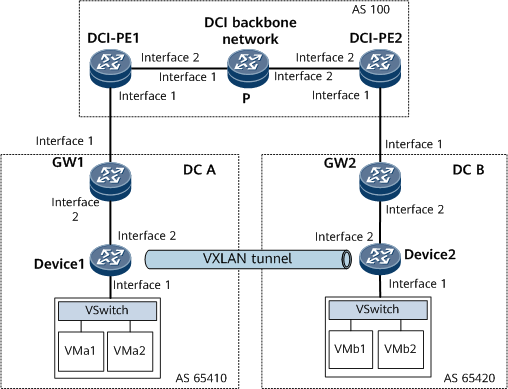
On the network shown in Figure 1, an end-to-end VXLAN tunnel can be established between Device1 and Device2 to implement communication between DC A and DC B. For example, VMa1 and VMb2 need to communicate with each other. To meet this requirement, establish a BGP EVPN peer relationship between Device1 and Device2 so that they can learn MAC and IP routes from each other. In addition, gateways GW1 and GW2 in the DCs are connected to DCI-PE1 and DCI-PE2, respectively, on the backbone network. An L3VPN based on an MPLS TE tunnel is established between DCI-PE1 and DCI-PE2 to transmit VXLAN packets (which can be considered as common IP packets).

Interfaces 1 and 2 in this example represent GE 0/1/0 and GE 0/1/8, respectively.
Device Name |
Interface Name |
IP Address |
|---|---|---|
DCI-PE1 |
GigabitEthernet 0/1/0 |
192.168.20.1/24 |
GigabitEthernet 0/1/8 |
192.168.1.1/24 |
|
LoopBack1 |
1.1.1.1/32 |
|
P |
GigabitEthernet 0/1/0 |
192.168.1.2/24 |
GigabitEthernet 0/1/8 |
192.168.10.1/24 |
|
LoopBack1 |
2.2.2.2/32 |
|
DCI-PE2 |
GigabitEthernet 0/1/0 |
192.168.30.1/24 |
GigabitEthernet 0/1/8 |
192.168.10.2/24 |
|
LoopBack1 |
3.3.3.3/32 |
|
GW1 |
GigabitEthernet 0/1/0 |
192.168.20.2/24 |
GigabitEthernet 0/1/8 |
192.168.40.1/24 |
|
LoopBack1 |
4.4.4.4/32 |
|
GW2 |
GigabitEthernet 0/1/0 |
192.168.30.2/24 |
GigabitEthernet 0/1/8 |
192.168.50.1/24 |
|
LoopBack1 |
7.7.7.7/32 |
|
Device1 |
GigabitEthernet 0/1/8 |
192.168.40.2/24 |
LoopBack1 |
5.5.5.5/32 |
|
Device2 |
GigabitEthernet 0/1/8 |
192.168.50.2/24 |
LoopBack1 |
6.6.6.6/32 |
Configuration Roadmap
The configuration roadmap is as follows:
- Configure an IGP in the data centers and on the DCI backbone network.
- Configure an MPLS TE tunnel on the DCI backbone network.
Configure a VPN instance on each DCI-PE and bind the interface connected to a gateway to the VPN instance.
Establish an MP-IBGP peer relationship between DCI-PEs for them to exchange VPNv4 routes.
Configure EBGP on DCI-PEs and gateways to exchange VPNv4 routes.
- Establish a BGP EVPN peer relationship between Device1 and Device2.
- Configure an end-to-end VXLAN tunnel between Device1 and Device2.
Data Preparation
To complete the configuration, you need the following data:
- VNIs on Device1 and Device2
MPLS LSR IDs of the DCI-PEs and P
Route distinguisher (RD) of a VPN instance
RTs used for route acceptance and advertisement
Procedure
- Assign an IP address to each interface on each node, and configure loopback interface addresses.
For configuration details, see Configuration Files in this section.
- Configure an IGP in the data centers and on the DCI backbone network. In this example, OSPF is used.
For configuration details, see Configuration Files in this section. On GW1 and GW2, import BGP routes to OSPF so that Device1 and Device2 can learn the IP routes destined for each other's VTEP address.
- Configure an MPLS TE tunnel on the DCI backbone network.
For configuration details, see Configuration Files in this section.
- Configure VPN instances on DCI-PEs, connect gateways to the DCI-PEs individually, and apply a tunnel policy.
# Configure DCI-PE1.
<DCI-PE1> system-view
[~DCI-PE1] tunnel-policy te-lsp1
[*DCI-PE1-tunnel-policy-te-lsp1] tunnel select-seq cr-lsp load-balance-number 1
[*DCI-PE1-tunnel-policy-te-lsp1] quit
[*DCI-PE1] ip vpn-instance vpn1
[*DCI-PE1-vpn-instance-vpn1] ipv4-family
[*DCI-PE1-vpn-instance-vpn1-af-ipv4] route-distinguisher 100:1
[*DCI-PE1-vpn-instance-vpn1-af-ipv4] tnl-policy te-lsp1
[*DCI-PE1-vpn-instance-vpn1-af-ipv4] vpn-target 111:1 both
[*DCI-PE1-vpn-instance-vpn1-af-ipv4] quit
[*DCI-PE1-vpn-instance-vpn1] quit
[*DCI-PE1] interface gigabitethernet 0/1/0
[*DCI-PE1-GigabitEthernet0/1/0] ip binding vpn-instance vpn1
[*DCI-PE1-GigabitEthernet0/1/0] ip address 192.168.20.1 24
[*DCI-PE1-GigabitEthernet0/1/0] quit
[*DCI-PE1] commit
# Configure DCI-PE2.
<DCI-PE2> system-view
[~DCI-PE2] tunnel-policy te-lsp1
[*DCI-PE2-tunnel-policy-te-lsp1] tunnel select-seq cr-lsp load-balance-number 1
[*DCI-PE2-tunnel-policy-te-lsp1] quit
[*DCI-PE2] ip vpn-instance vpn1
[*DCI-PE2-vpn-instance-vpn1] ipv4-family
[*DCI-PE2-vpn-instance-vpn1-af-ipv4] route-distinguisher 200:1
[*DCI-PE2-vpn-instance-vpn1-af-ipv4] tnl-policy te-lsp1
[*DCI-PE2-vpn-instance-vpn1-af-ipv4] vpn-target 111:1 both
[*DCI-PE2-vpn-instance-vpn1-af-ipv4] quit
[*DCI-PE2-vpn-instance-vpn1] quit
[*DCI-PE2] interface gigabitethernet 0/1/0
[*DCI-PE2-GigabitEthernet0/1/0] ip binding vpn-instance vpn1
[*DCI-PE2-GigabitEthernet0/1/0] ip address 192.168.30.1 24
[*DCI-PE2-GigabitEthernet0/1/0] quit
[*DCI-PE2] commit
- Set up an EBGP peer relationship between each DCI-PE and its connected gateway.
# Configure DCI-PE1.
[~DCI-PE1] bgp 100
[*DCI-PE1-bgp] ipv4-family vpn-instance vpn1
[*DCI-PE1-bgp-vpn1] peer 192.168.20.2 as-number 65410
[*DCI-PE1-bgp-vpn1] quit
[*DCI-PE1] commit
# Configure DCI-PE2.
[~DCI-PE2] bgp 100
[*DCI-PE2-bgp] ipv4-family vpn-instance vpn1
[*DCI-PE2-bgp-vpn1] peer 192.168.30.2 as-number 65420
[*DCI-PE2-bgp-vpn1] quit
[*DCI-PE2] commit
- Set up an MP-IBGP peer relationship between DCI-PEs.
# Configure DCI-PE1.
[~DCI-PE1] bgp 100
[*DCI-PE1-bgp] peer 3.3.3.3 as-number 100
[*DCI-PE1-bgp] peer 3.3.3.3 connect-interface loopback 1
[*DCI-PE1-bgp] ipv4-family vpnv4
[*DCI-PE1-bgp-af-vpnv4] peer 3.3.3.3 enable
[*DCI-PE1-bgp-af-vpnv4] quit
[*DCI-PE1-bgp] quit
[*DCI-PE1] commit
# Configure DCI-PE2.
[~DCI-PE2] bgp 100
[*DCI-PE2-bgp] peer 1.1.1.1 as-number 100
[*DCI-PE2-bgp] peer 1.1.1.1 connect-interface loopback 1
[*DCI-PE2-bgp] ipv4-family vpnv4
[*DCI-PE2-bgp-af-vpnv4] peer 1.1.1.1 enable
[*DCI-PE2-bgp-af-vpnv4] quit
[*DCI-PE2-bgp] quit
[*DCI-PE2] commit
- Establish a BGP EVPN peer relationship between Device1 and Device2.
# Configure Device1.
<Device1> system-view
[~Device1] bgp 65410
[*Device1-bgp] peer 4.4.4.4 as-number 65410
[*Device1-bgp] peer 4.4.4.4 connect-interface LoopBack1
[*Device1-bgp] peer 6.6.6.6 as-number 65420
[*Device1-bgp] peer 6.6.6.6 ebgp-max-hop 255
[*Device1-bgp] peer 6.6.6.6 connect-interface LoopBack1
[*Device1-bgp] l2vpn-family evpn
[*Device1-bgp-bgp-af-evpn] peer 6.6.6.6 enable
[*Device1-bgp-bgp-af-evpn] peer 6.6.6.6 next-hop-invariable
[*Device1-bgp-bgp-af-evpn] peer 6.6.6.6 advertise encap-type vxlan
[*Device1-bgp-bgp-af-evpn] quit
[*Device1-bgp] quit
[*Device1] commit
# Configure Device2.
<Device2> system-view
[~Device2] bgp 65420
[*Device2-bgp] peer 7.7.7.7 as-number 65420
[*Device2-bgp] peer 7.7.7.7 connect-interface LoopBack1
[*Device2-bgp] peer 5.5.5.5 as-number 65410
[*Device2-bgp] peer 5.5.5.5 ebgp-max-hop 255
[*Device2-bgp] peer 5.5.5.5 connect-interface LoopBack1
[*Device2-bgp] l2vpn-family evpn
[*Device2-bgp-bgp-af-evpn] peer 5.5.5.5 enable
[*Device2-bgp-bgp-af-evpn] peer 5.5.5.5 next-hop-invariable
[*Device2-bgp-bgp-af-evpn] peer 5.5.5.5 advertise encap-type vxlan
[*Device2-bgp-bgp-af-evpn] quit
[*Device2-bgp] quit
[*Device2] commit
# Configure GW1. To enable the remote Device2 to learn the IP route to the VTEP address on the local Device1, GW1 needs to import the involved OSPF route into BGP.
<GW1> system-view
[~GW1] bgp 65410
[*GW1-bgp] peer 5.5.5.5 as-number 65410
[*GW1-bgp] peer 5.5.5.5 connect-interface LoopBack1
[*GW1-bgp] peer 192.168.20.1 as-number 100
[*GW1-bgp] network 4.4.4.4 32
[*GW1-bgp] import-route ospf 1
[*GW1-bgp] quit
[*GW1] commit
# Configure GW2. To enable the remote Device1 to learn the IP route to the VTEP address on the local Device2, GW2 needs to import the involved OSPF route into BGP.
<GW1> system-view
[~GW2] bgp 65420
[*GW2-bgp] peer 6.6.6.6 as-number 65420
[*GW2-bgp] peer 6.6.6.6 connect-interface LoopBack1
[*GW2-bgp] peer 192.168.30.1 as-number 100
[*GW2-bgp] network 7.7.7.7 32
[*GW2-bgp] import-route ospf 1
[*GW2-bgp] quit
[*GW2] commit
- Configure an EVPN instance on Device1 and Device2.
# Configure Device1.
[~Device1] evpn vpn-instance evrf1 bd-mode
[*Device1-evpn-instance-evrf1] route-distinguisher 10:1
[*Device1-evpn-instance-evrf1] vpn-target 11:1 both
[*Device1-evpn-instance-evrf1] quit
[*Device1] bridge-domain 10
[*Device1-bd10] vxlan vni 10 split-horizon-mode
[*Device1-bd10] evpn binding vpn-instance evrf1
[*Device1-bd10] quit
[*Device1] commit
# Configure Device2.
[~Device2] evpn vpn-instance evrf1 bd-mode
[*Device2-evpn-instance-evrf1] route-distinguisher 20:1
[*Device2-evpn-instance-evrf1] vpn-target 11:1 both
[*Device2-evpn-instance-evrf1] quit
[*Device2] bridge-domain 10
[*Device2-bd10] vxlan vni 10 split-horizon-mode
[*Device2-bd10] evpn binding vpn-instance evrf1
[*Device2-bd10] quit
[*Device2] commit
- Configure a VXLAN tunnel between Device1 and Device2.
# Configure Device1.
[~Device1] interface nve 1
[*Device1-Nve1] source 5.5.5.5
[*Device1-Nve1] vni 10 head-end peer-list protocol bgp
[*Device1-Nve1] quit
[*Device1] commit
# Configure Device2.
[~Device2] interface nve 1
[*Device2-Nve1] source 6.6.6.6
[*Device2-Nve1] vni 10 head-end peer-list protocol bgp
[*Device2-Nve1] quit
[*Device2] commit
- Configure service access points on Device1 and Device2 and connect them to VMs through Layer 2 sub-interfaces.
# Configure Device1.
[~Device1] interface gigabitethernet 0/1/0.1 mode l2
[*Device1-GigabitEthernet 0/1/0.1] encapsulation dot1q vid 10
[*Device1-GigabitEthernet 0/1/0.1] rewrite pop single
[*Device1-GigabitEthernet 0/1/0.1] bridge-domain 10
[*Device1-GigabitEthernet 0/1/0.1] quit
[*Device1] commit
# Configure Device2.
[~Device2] interface gigabitethernet 0/1/0.1 mode l2
[*Device2-GigabitEthernet 0/1/0.1] encapsulation dot1q vid 10
[*Device2-GigabitEthernet 0/1/0.1] rewrite pop single
[*Device2-GigabitEthernet 0/1/0.1] bridge-domain 10
[*Device2-GigabitEthernet 0/1/0.1] quit
[*Device2] commit
- Verify the configuration.
Run the display bgp evpn peer command on Device1. The command output shows that Device1 has established a BGP EVPN peer relationship with Device2.
[~Device1] display bgp evpn peer
 Total number of peers : 1                 Peers in established state : 1

  Peer                             V          AS  MsgRcvd  MsgSent  OutQ  Up/Down       State  PrefRcv
  6.6.6.6                          4       65420      711      711     0 10:14:35 Established        2
Run the display vxlan tunnel command on Device1. The command output shows that an end-to-end VXLAN tunnel has been established between Device1 and Device2.
[~Device1] display vxlan tunnel
Number of vxlan tunnel : 1
Tunnel ID   Source                Destination           State  Type     Uptime
-----------------------------------------------------------------------------------
4026531843  5.5.5.5               6.6.6.6               up     dynamic  10:17:15
Configuration Files
- Device1 configuration file
#
sysname Device1
#
evpn vpn-instance evrf1 bd-mode
 route-distinguisher 10:1
 vpn-target 11:1 export-extcommunity
 vpn-target 11:1 import-extcommunity
#
bridge-domain 10
 vxlan vni 10 split-horizon-mode
 evpn binding vpn-instance evrf1
#
interface GigabitEthernet0/1/0
 undo shutdown
#
interface GigabitEthernet0/1/0.1 mode l2
 encapsulation dot1q vid 10
 rewrite pop single
 bridge-domain 10
#
interface GigabitEthernet0/1/8
 undo shutdown
 ip address 192.168.40.2 255.255.255.0
#
interface LoopBack1
 ip address 5.5.5.5 255.255.255.255
#
interface Nve1
 source 5.5.5.5
 vni 10 head-end peer-list protocol bgp
#
bgp 65410
 peer 4.4.4.4 as-number 65410
 peer 4.4.4.4 connect-interface LoopBack1
 peer 6.6.6.6 as-number 65420
 peer 6.6.6.6 ebgp-max-hop 255
 peer 6.6.6.6 connect-interface LoopBack1
 #
 ipv4-family unicast
  undo synchronization
  peer 4.4.4.4 enable
  peer 6.6.6.6 enable
 #
 l2vpn-family evpn
  policy vpn-target
  peer 6.6.6.6 enable
  peer 6.6.6.6 next-hop-invariable
  peer 6.6.6.6 advertise encap-type vxlan
#
ospf 1
 area 0.0.0.0
  network 5.5.5.5 0.0.0.0
  network 192.168.40.0 0.0.0.255
#
return
- Device2 configuration file
#
sysname Device2
#
evpn vpn-instance evrf1 bd-mode
 route-distinguisher 20:1
 vpn-target 11:1 export-extcommunity
 vpn-target 11:1 import-extcommunity
#
bridge-domain 10
 vxlan vni 10 split-horizon-mode
 evpn binding vpn-instance evrf1
#
interface GigabitEthernet0/1/0
 undo shutdown
#
interface GigabitEthernet0/1/0.1 mode l2
 encapsulation dot1q vid 10
 rewrite pop single
 bridge-domain 10
#
interface GigabitEthernet0/1/8
 undo shutdown
 ip address 192.168.50.2 255.255.255.0
#
interface LoopBack1
 ip address 6.6.6.6 255.255.255.255
#
interface Nve1
 source 6.6.6.6
 vni 10 head-end peer-list protocol bgp
#
bgp 65420
 peer 5.5.5.5 as-number 65410
 peer 5.5.5.5 ebgp-max-hop 255
 peer 5.5.5.5 connect-interface LoopBack1
 peer 7.7.7.7 as-number 65420
 peer 7.7.7.7 connect-interface LoopBack1
 #
 ipv4-family unicast
  undo synchronization
  peer 5.5.5.5 enable
  peer 7.7.7.7 enable
 #
 l2vpn-family evpn
  policy vpn-target
  peer 5.5.5.5 enable
  peer 5.5.5.5 next-hop-invariable
  peer 5.5.5.5 advertise encap-type vxlan
#
ospf 1
 area 0.0.0.0
  network 6.6.6.6 0.0.0.0
  network 192.168.50.0 0.0.0.255
#
return
- GW1 configuration file
#
sysname GW1
#
interface GigabitEthernet0/1/0
 undo shutdown
 ip address 192.168.20.2 255.255.255.0
#
interface GigabitEthernet0/1/8
 undo shutdown
 ip address 192.168.40.1 255.255.255.0
#
interface LoopBack1
 ip address 4.4.4.4 255.255.255.255
#
bgp 65410
 peer 5.5.5.5 as-number 65410
 peer 5.5.5.5 connect-interface LoopBack1
 peer 192.168.20.1 as-number 100
 #
 ipv4-family unicast
  undo synchronization
  network 4.4.4.4 255.255.255.255
  import-route ospf 1
  peer 5.5.5.5 enable
  peer 192.168.20.1 enable
#
ospf 1
 import-route bgp
 area 0.0.0.0
  network 4.4.4.4 0.0.0.0
  network 192.168.40.0 0.0.0.255
#
return
- GW2 configuration file
#
sysname GW2
#
interface GigabitEthernet0/1/0
 undo shutdown
 ip address 192.168.30.2 255.255.255.0
#
interface GigabitEthernet0/1/8
 undo shutdown
 ip address 192.168.50.1 255.255.255.0
#
interface LoopBack1
 ip address 7.7.7.7 255.255.255.255
#
bgp 65420
 peer 6.6.6.6 as-number 65420
 peer 6.6.6.6 connect-interface LoopBack1
 peer 192.168.30.1 as-number 100
 #
 ipv4-family unicast
  undo synchronization
  network 7.7.7.7 255.255.255.255
  import-route ospf 1
  peer 6.6.6.6 enable
  peer 192.168.30.1 enable
#
ospf 1
 import-route bgp
 area 0.0.0.0
  network 7.7.7.7 0.0.0.0
  network 192.168.50.0 0.0.0.255
#
return
DCI-PE1 configuration file
#
sysname DCI-PE1
#
ip vpn-instance vpn1
 ipv4-family
  route-distinguisher 100:1
  apply-label per-instance
  tnl-policy te-lsp1
  vpn-target 111:1 export-extcommunity
  vpn-target 111:1 import-extcommunity
#
mpls lsr-id 1.1.1.1
#
mpls
 mpls te
 mpls te cspf
 mpls rsvp-te
#
interface GigabitEthernet0/1/0
 undo shutdown
 ip binding vpn-instance vpn1
 ip address 192.168.20.1 255.255.255.0
#
interface GigabitEthernet0/1/8
 undo shutdown
 ip address 192.168.1.1 255.255.255.0
 mpls
 mpls te
 mpls rsvp-te
#
interface LoopBack1
 ip address 1.1.1.1 255.255.255.255
#
interface Tunnel10
 ip address unnumbered interface LoopBack1
 tunnel-protocol mpls te
 destination 3.3.3.3
 mpls te tunnel-id 100
#
bgp 100
 peer 3.3.3.3 as-number 100
 peer 3.3.3.3 connect-interface LoopBack1
#
 ipv4-family unicast
  peer 3.3.3.3 enable
#
 ipv4-family vpnv4
  policy vpn-target
  peer 3.3.3.3 enable
 #
 ipv4-family vpn-instance vpn1
  peer 192.168.20.2 as-number 65410
#
ospf 1
 opaque-capability enable
 area 0.0.0.0
  network 1.1.1.1 0.0.0.0
  network 192.168.1.0 0.0.0.255
  mpls-te enable
#
tunnel-policy te-lsp1
 tunnel select-seq cr-lsp load-balance-number 1
#
return
P configuration file
#
sysname P
#
mpls lsr-id 2.2.2.2
#
mpls
 mpls te
 mpls te cspf
 mpls rsvp-te
#
interface GigabitEthernet0/1/0
 undo shutdown
 ip address 192.168.1.2 255.255.255.0
 mpls
 mpls te
 mpls rsvp-te
#
interface GigabitEthernet0/1/8
 undo shutdown
 ip address 192.168.10.1 255.255.255.0
 mpls
 mpls te
 mpls rsvp-te
#
interface LoopBack1
 ip address 2.2.2.2 255.255.255.255
#
ospf 1
 opaque-capability enable
 area 0.0.0.0
  network 2.2.2.2 0.0.0.0
  network 192.168.1.0 0.0.0.255
  network 192.168.10.0 0.0.0.255
  mpls-te enable
#
return
DCI-PE2 configuration file
#
sysname DCI-PE2
#
ip vpn-instance vpn1
 ipv4-family
  route-distinguisher 200:1
  apply-label per-instance
  tnl-policy te-lsp1
  vpn-target 111:1 export-extcommunity
  vpn-target 111:1 import-extcommunity
#
mpls lsr-id 3.3.3.3
#
mpls
 mpls te
 mpls te cspf
 mpls rsvp-te
#
interface GigabitEthernet0/1/0
 undo shutdown
 ip binding vpn-instance vpn1
 ip address 192.168.30.1 255.255.255.0
#
interface GigabitEthernet0/1/8
 undo shutdown
 ip address 192.168.10.2 255.255.255.0
 mpls
 mpls te
 mpls rsvp-te
#
interface LoopBack1
 ip address 3.3.3.3 255.255.255.255
#
interface Tunnel10
 ip address unnumbered interface LoopBack1
 tunnel-protocol mpls te
 destination 1.1.1.1
 mpls te tunnel-id 100
#
bgp 100
 peer 1.1.1.1 as-number 100
 peer 1.1.1.1 connect-interface LoopBack1
 #
 ipv4-family unicast
  peer 1.1.1.1 enable
 #
 ipv4-family vpnv4
  policy vpn-target
  peer 1.1.1.1 enable
 #
 ipv4-family vpn-instance vpn1
  peer 192.168.30.2 as-number 65420
 #
ospf 1
 opaque-capability enable
 area 0.0.0.0
  network 3.3.3.3 0.0.0.0
  network 192.168.10.0 0.0.0.255
  mpls-te enable
#
tunnel-policy te-lsp1
 tunnel select-seq cr-lsp load-balance-number 1
#
return