Example for Configuring a DCI Scenario with a VXLAN EVPN L3VPN Accessing a Common L3VPN
This section provides an example for configuring a DCI scenario with a VXLAN EVPN L3VPN accessing a common L3VPN. In this example, a data center gateway is connected to a PE on the DCI network through a VXLAN tunnel, and a common L3VPN is deployed on the DCI network to implement data center interconnection.
Networking Requirements
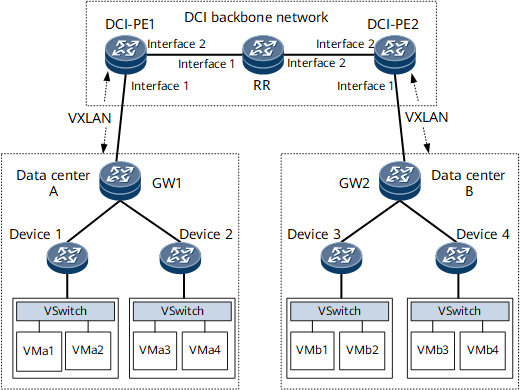
In Figure 1, data center gateway devices GW1 and GW2 are connected to the DCI backbone network. To allow inter-data center VM communication (for example, VMa1 and VMb2 communication), BGP/MPLS IP VPN functions must be deployed on the DCI backbone network, and EVPN and VXLAN tunnels must be deployed between the GW and DCI-PE to transmit VM host IP route information.

Interfaces 1 and 2 in this example represent GE 0/1/0 and GE 0/1/8, respectively.
Device |
Interface Name |
IP Address |
|---|---|---|
DCI-PE1 |
GigabitEthernet 0/1/0 |
192.168.20.1/24 |
GigabitEthernet 0/1/8 |
192.168.1.1/24 |
|
LoopBack1 |
1.1.1.1/32 |
|
LoopBack2 |
11.11.11.11/32 |
|
RR |
GigabitEthernet 0/1/0 |
192.168.1.2/24 |
GigabitEthernet 0/1/8 |
192.168.10.1/24 |
|
LoopBack1 |
2.2.2.2/32 |
|
DCI-PE2 |
GigabitEthernet 0/1/0 |
192.168.30.1/24 |
GigabitEthernet 0/1/8 |
192.168.10.2/24 |
|
LoopBack1 |
3.3.3.3/32 |
|
LoopBack2 |
33.33.33.33/32 |
Configuration Roadmap
The configuration roadmap is as follows:
Enable OSPF on the DCI backbone network for DCI-PEs to communicate with each other.
Configure an MPLS TE tunnel on the DCI backbone network.
Configure static routes on the DCI-PEs destined for the loopback interface addresses of the DC-GWs.
Configure an EVPN instance and a BD on each DCI-PE.
Configure a source address on each DCI-PE.
Configure VXLAN tunnels between DCI-PEs and GWs.
Configure a VPN instance on each DCI-PE and bind the interface connected to a GW to the VPN instance.
Configure an MP-IBGP peer relationship between each DCI-PE and RR to exchange VPNv4 routes and configure RR in the figure as a route reflector.
Configure the route regeneration function on each DCI-PE-GW.
Data Preparation
To complete the configuration, you need the following data:
MPLS LSR IDs of the DCI-PEs and RR
RD of a VPN instance
VPN targets
Procedure
- Assign an IP address to each interface on each node, and configure loopback interface addresses.
For configuration details, see Configuration Files in this section.
- Configure an IGP on the DCI backbone network. OSPF is used as an IGP in this example.
For configuration details, see Configuration Files in this section.
- Configure an MPLS TE tunnel on the DCI backbone network.
For configuration details, see Configuration Files in this section.
- On each DCI-PE, configure a static route destined for the loopback interface of the connected DC-GW.
For configuration details, see Configuration Files in this section.
- Configure an EVPN instance and a BD on each DCI-PE.
# Configure DCI-PE1.
[~DCI-PE1] evpn vpn-instance evrf1 bd-mode
[*DCI-PE1-evpn-instance-evrf1] route-distinguisher 10:1
[*DCI-PE1-evpn-instance-evrf1] vpn-target 11:1 both
[*DCI-PE1-evpn-instance-evrf1] quit
[*DCI-PE1] bridge-domain 10
[*DCI-PE1-bd10] vxlan vni 5010 split-horizon-mode
[*DCI-PE1-bd10] evpn binding vpn-instance evrf1
[*DCI-PE1-bd10] esi 0000.1111.1111.4444.5555
[*DCI-PE1-bd10] quit
[*DCI-PE1] interface GigabitEthernet 0/1/0.1 mode l2
[*DCI-PE1-GigabitEthernet0/1/0.1] encapsulation qinq
[*DCI-PE1-GigabitEthernet0/1/0.1] bridge-domain 10
[*DCI-PE1-GigabitEthernet0/1/0.1] quit
[*DCI-PE1] commit
# Configure DCI-PE2.
[~DCI-PE2] evpn vpn-instance evrf1 bd-mode
[*DCI-PE2-evpn-instance-evrf1] route-distinguisher 20:1
[*DCI-PE2-evpn-instance-evrf1] vpn-target 11:1 both
[*DCI-PE2-evpn-instance-evrf1] quit
[*DCI-PE2] bridge-domain 10
[*DCI-PE2-bd10] vxlan vni 5020 split-horizon-mode
[*DCI-PE2-bd10] evpn binding vpn-instance evrf1
[*DCI-PE2-bd10] esi 0000.1111.3333.4444.5555
[*DCI-PE2-bd10] quit
[*DCI-PE2] interface GigabitEthernet 0/1/0.1 mode l2
[*DCI-PE2-GigabitEthernet0/1/0.1] encapsulation qinq
[*DCI-PE2-GigabitEthernet0/1/0.1] bridge-domain 10
[*DCI-PE2-GigabitEthernet0/1/0.1] quit
[*DCI-PE2] commit
- Configure a source address on each DCI-PE.
# Configure DCI-PE1.
[~DCI-PE1] evpn source-address 1.1.1.1
[*DCI-PE1] commit
# Configure DCI-PE2.
[~DCI-PE2] evpn source-address 3.3.3.3
[*DCI-PE2] commit
- Establish a VXLAN tunnel.
- Configure a VPN instance on each DCI-PE to apply a tunnel policy.
# Configure DCI-PE1.
[~DCI-PE1] tunnel-policy te-lsp1
[*DCI-PE1-tunnel-policy-te-lsp1] tunnel select-seq cr-lsp load-balance-number 1
[*DCI-PE1-tunnel-policy-te-lsp1] quit
[*DCI-PE1] ip vpn-instance vpn1
[*DCI-PE1-vpn-instance-vpn1] ipv4-family
[*DCI-PE1-vpn-instance-vpn1-af-ipv4] tnl-policy te-lsp1
[*DCI-PE1-vpn-instance-vpn1-af-ipv4] quit
[*DCI-PE1-vpn-instance-vpn1] quit
[*DCI-PE1] commit
# Configure DCI-PE2.
[~DCI-PE2] tunnel-policy te-lsp1
[*DCI-PE2-tunnel-policy-te-lsp1] tunnel select-seq cr-lsp load-balance-number 1
[*DCI-PE2-tunnel-policy-te-lsp1] quit
[*DCI-PE2] ip vpn-instance vpn1
[*DCI-PE2-vpn-instance-vpn1] ipv4-family
[*DCI-PE2-vpn-instance-vpn1-af-ipv4] tnl-policy te-lsp1
[*DCI-PE2-vpn-instance-vpn1-af-ipv4] quit
[*DCI-PE2-vpn-instance-vpn1] quit
[*DCI-PE2] commit
- Configure an MP-IBGP peer relationship between each DCI-PE and RR to exchange VPNv4 routes and configure RR in the figure as a route reflector.
# Configure DCI-PE1.
[~DCI-PE1] bgp 100
[*DCI-PE1-bgp] peer 2.2.2.2 as-number 100
[*DCI-PE1-bgp] peer 2.2.2.2 connect-interface loopback 1
[*DCI-PE1-bgp] ipv4-family vpnv4
[*DCI-PE1-bgp-af-vpnv4] peer 2.2.2.2 enable
[*DCI-PE1-bgp-af-vpnv4] quit
[*DCI-PE1-bgp] quit
[*DCI-PE1] commit
# Configure RR.
[~RR] bgp 100
[*RR-bgp] peer 1.1.1.1 as-number 100
[*RR-bgp] peer 1.1.1.1 connect-interface loopback 1
[*RR-bgp] peer 3.3.3.3 as-number 100
[*RR-bgp] peer 3.3.3.3 connect-interface loopback 1
[*RR-bgp] ipv4-family vpnv4
[*RR-bgp-af-vpnv4] peer 1.1.1.1 enable
[*RR-bgp-af-vpnv4] peer 1.1.1.1 reflect-client
[*RR-bgp-af-vpnv4] peer 3.3.3.3 enable
[*RR-bgp-af-vpnv4] peer 3.3.3.3 reflect-client
[*RR-bgp-af-vpnv4] quit
[*RR-bgp] quit
[*RR] commit
# Configure DCI-PE2.
[~DCI-PE2] bgp 100
[*DCI-PE2-bgp] peer 2.2.2.2 as-number 100
[*DCI-PE2-bgp] peer 2.2.2.2 connect-interface loopback 1
[*DCI-PE2-bgp] ipv4-family vpnv4
[*DCI-PE2-bgp-af-vpnv4] peer 2.2.2.2 enable
[*DCI-PE2-bgp-af-vpnv4] quit
[*DCI-PE2-bgp] quit
[*DCI-PE2] commit
- Configure each DCI-PE to send regenerated EVPN routes to VPNv4 peers and to send regenerated VPNv4 routes to EVPN peers.
# Configure DCI-PE1.
[~DCI-PE1] bgp 100
[*DCI-PE1-bgp] l2vpn-family evpn
[*DCI-PE1-bgp-af-evpn] peer 4.4.4.4 import reoriginate
[*DCI-PE1-bgp-af-evpn] peer 4.4.4.4 advertise route-reoriginated vpnv4
[*DCI-PE1-bgp-af-evpn] quit
[*DCI-PE1-bgp] ipv4-family vpnv4
[*DCI-PE1-bgp-af-vpnv4] peer 3.3.3.3 advertise route-reoriginated evpn mac-ip
[*DCI-PE1-bgp-af-vpnv4] peer 3.3.3.3 advertise route-reoriginated evpn ip
[*DCI-PE1-bgp-af-vpnv4] peer 3.3.3.3 import reoriginate
[*DCI-PE1-bgp-af-vpnv4] quit
[*DCI-PE1-bgp] ipv4-family vpn-instance vpn1
[*DCI-PE1-bgp-vpn1] advertise l2vpn evpn
[*DCI-PE1-bgp-vpn1] quit
[*DCI-PE1-bgp] quit
[*DCI-PE1] commit
# Configure DCI-PE2.
[~DCI-PE1] bgp 100
[*DCI-PE1-bgp] l2vpn-family evpn
[*DCI-PE1-bgp-af-evpn] peer 5.5.5.5 import reoriginate
[*DCI-PE1-bgp-af-evpn] peer 5.5.5.5 advertise route-reoriginated vpnv4
[*DCI-PE1-bgp-af-evpn] quit
[*DCI-PE2-bgp] ipv4-family vpnv4
[*DCI-PE2-bgp-af-vpnv4] peer 1.1.1.1 import reoriginate
[*DCI-PE2-bgp-af-vpnv4] peer 1.1.1.1 advertise route-reoriginated evpn mac-ip
[*DCI-PE2-bgp-af-vpnv4] peer 1.1.1.1 advertise route-reoriginated evpn ip
[*DCI-PE2-bgp-af-vpnv4] quit
[*DCI-PE2-bgp] ipv4-family vpn-instance vpn1
[*DCI-PE2-bgp-vpn1] advertise l2vpn evpn
[*DCI-PE2-bgp-vpn1] quit
[*DCI-PE2-bgp] quit
[*DCI-PE2] commit
- Verify the configuration.
Run the display ip routing-table vpn-instance command on DCI-PEs. The following example uses the command output on DCI-PE1. The command output shows that DCI-PE1 has a route to the loopback interface of GW1.
[~DCI-PE1] display ip routing-table vpn-instance vpn1
Route Flags: R - relay, D - download to fib, T - to vpn-instance, B - black hole route
------------------------------------------------------------------------------
Routing Table : vpn1
         Destinations : 6        Routes : 6

Destination/Mask    Proto   Pre  Cost        Flags NextHop         Interface

       10.1.1.0/24  EBGP    255  0             RD  4.4.4.4         VXLAN
       10.1.1.1/32  EBGP    255  0             RD  4.4.4.4         VXLAN
      10.2.1.0/24  IBGP    255  0             RD  3.3.3.3         Tunnel10
      10.2.1.1/32  IBGP    255  0             RD  3.3.3.3         Tunnel10
      127.0.0.0/8   Direct  0    0             D   127.0.0.1       InLoopBack0
255.255.255.255/32  Direct  0    0             D   127.0.0.1       InLoopBack0
Run the display vxlan tunnel command on DCI-PEs to check information about the VXLAN tunnel. The following example uses the command output on DCI-PE1.
[~DCI-PE1] display vxlan tunnel
Number of vxlan tunnel : 1
Tunnel ID   Source                Destination           State  Type     Uptime
-----------------------------------------------------------------------------------
4026531843  11.11.11.11           4.4.4.4               up     dynamic  00:51:23
Configuration Files
DCI-PE1 configuration file
#
sysname DCI-PE1
#
evpn vpn-instance evrf1 bd-mode
 route-distinguisher 10:1
 vpn-target 11:1 export-extcommunity
 vpn-target 11:1 import-extcommunity
#
ip vpn-instance vpn1
 ipv4-family
  route-distinguisher 11:11
  apply-label per-instance
  tnl-policy te-lsp1
  vpn-target 1:1 export-extcommunity
  vpn-target 11:1 export-extcommunity evpn
  vpn-target 1:1 import-extcommunity
  vpn-target 11:1 import-extcommunity evpn
 vxlan vni 555
#
mpls lsr-id 1.1.1.1
#
mpls
 mpls te
 mpls rsvp-te
 mpls te cspf
#
bridge-domain 10
 vxlan vni 5010 split-horizon-mode
 evpn binding vpn-instance evrf1
 esi 0000.1111.1111.4444.5555
#
interface Vbdif10
 ip binding vpn-instance vpn1
 ip address 10.10.10.1 255.255.255.0
 arp collect host enable
#
interface GigabitEthernet0/1/0
 undo shutdown
 ip address 192.168.20.1 255.255.255.0
#
interface GigabitEthernet0/1/0.1 mode l2
 encapsulation qinq
 bridge-domain 10
#
interface GigabitEthernet0/1/8
 undo shutdown
 ip address 192.168.1.1 255.255.255.0
 mpls
 mpls te
 mpls rsvp-te
#
interface LoopBack1
 ip address 1.1.1.1 255.255.255.255
 isis enable 1
#
interface LoopBack2
 ip address 11.11.11.11 255.255.255.255
#
interface Nve1
 source 11.11.11.11
#
interface Tunnel10
 ip address unnumbered interface LoopBack1
 tunnel-protocol mpls te
 destination 3.3.3.3
 mpls te tunnel-id 100
#
bgp 100
 peer 2.2.2.2 as-number 100
 peer 2.2.2.2 connect-interface LoopBack1
 peer 4.4.4.4 as-number 65410
 peer 4.4.4.4 ebgp-max-hop 255
 peer 4.4.4.4 connect-interface LoopBack2
 #
 ipv4-family unicast
  undo synchronization
  peer 2.2.2.2 enable
  peer 4.4.4.4 enable
 #
 ipv4-family vpnv4
  policy vpn-target
  peer 2.2.2.2 enable
  peer 2.2.2.2 import reoriginate
  peer 2.2.2.2 advertise route-reoriginated evpn mac-ip
  peer 2.2.2.2 advertise route-reoriginated evpn ip
 #
 ipv4-family vpn-instance vpn1
  advertise l2vpn evpn
 #
 l2vpn-family evpn
  undo policy vpn-target
  peer 4.4.4.4 enable
  peer 4.4.4.4 advertise encap-type vxlan
  peer 4.4.4.4 import reoriginate
  peer 4.4.4.4 advertise route-reoriginated vpnv4
#
ospf 1
 opaque-capability enable
 area 0.0.0.0
  network 1.1.1.1 0.0.0.0
  network 192.168.1.0 0.0.0.255
  mpls-te enable
#
ip route-static 4.4.4.4 255.255.255.255 192.168.20.2
#
tunnel-policy te-lsp1
 tunnel select-seq cr-lsp load-balance-number 1
#
evpn source-address 1.1.1.1
#
return
RR configuration file
#
sysname RR
#
mpls lsr-id 2.2.2.2
#
mpls
 mpls te
 mpls rsvp-te
 mpls te cspf
#
interface GigabitEthernet0/1/0
 undo shutdown
 ip address 192.168.1.2 255.255.255.0
 mpls
 mpls te
 mpls rsvp-te
#
interface GigabitEthernet0/1/8
 undo shutdown
 ip address 192.168.10.1 255.255.255.0
 mpls
 mpls te
 mpls rsvp-te
#
interface LoopBack1
 ip address 2.2.2.2 255.255.255.255
#
bgp 100
 peer 1.1.1.1 as-number 100
 peer 1.1.1.1 connect-interface LoopBack1
 peer 3.3.3.3 as-number 100
 #
 ipv4-family unicast
  undo synchronization
  peer 1.1.1.1 enable
  peer 3.3.3.3 enable
 #
 ipv4-family vpnv4
  undo policy vpn-target
  peer 1.1.1.1 enable
  peer 1.1.1.1 reflect-client
  peer 3.3.3.3 enable
  peer 3.3.3.3 reflect-client
#
ospf 1
 opaque-capability enable
 area 0.0.0.0
  network 2.2.2.2 0.0.0.0
  network 192.168.1.0 0.0.0.255
  network 192.168.10.0 0.0.0.255
  mpls-te enable
#
return
DCI-PE2 configuration file
#
sysname DCI-PE2
#
evpn vpn-instance evrf1 bd-mode
 route-distinguisher 20:1
 vpn-target 11:1 export-extcommunity
 vpn-target 11:1 import-extcommunity
#
ip vpn-instance vpn1
 ipv4-family
  route-distinguisher 22:22
  apply-label per-instance
  tnl-policy te-lsp1
  vpn-target 1:1 export-extcommunity
  vpn-target 11:1 export-extcommunity evpn
  vpn-target 1:1 import-extcommunity
  vpn-target 11:1 import-extcommunity evpn
 vxlan vni 555
#
mpls lsr-id 3.3.3.3
#
mpls
 mpls te
 mpls rsvp-te
 mpls te cspf
#
bridge-domain 10
 vxlan vni 5020 split-horizon-mode
 evpn binding vpn-instance evrf1
 esi 0000.1111.3333.4444.5555
#
interface Vbdif10
 ip binding vpn-instance vpn1
 ip address 10.20.10.1 255.255.255.0
 arp collect host enable
#
interface GigabitEthernet0/1/0
 undo shutdown
 ip address 192.168.30.1 255.255.255.0
#
interface GigabitEthernet0/1/0.1 mode l2
 encapsulation qinq
 bridge-domain 10
#
interface GigabitEthernet0/1/8
 undo shutdown
 ip address 192.168.10.2 255.255.255.0
 mpls
 mpls te
 mpls rsvp-te
#
interface LoopBack1
 ip address 3.3.3.3 255.255.255.255
 isis enable 1
#
interface LoopBack2
 ip address 33.33.33.33 255.255.255.255
#
interface Nve1
 source 33.33.33.33
#
interface Tunnel10
 ip address unnumbered interface LoopBack1
 tunnel-protocol mpls te
 destination 1.1.1.1
 mpls te tunnel-id 100
#
bgp 100
 peer 2.2.2.2 as-number 100
 peer 2.2.2.2 connect-interface LoopBack1
 peer 5.5.5.5 as-number 65420
 peer 5.5.5.5 ebgp-max-hop 255
 peer 5.5.5.5 connect-interface LoopBack2
 #
 ipv4-family unicast
  undo synchronization
  peer 2.2.2.2 enable
  peer 5.5.5.5 enable
 #
 ipv4-family vpnv4
  policy vpn-target
  peer 2.2.2.2 enable
  peer 2.2.2.2 import reoriginate
  peer 2.2.2.2 advertise route-reoriginated evpn mac-ip
  peer 2.2.2.2 advertise route-reoriginated evpn ip
 #
 ipv4-family vpn-instance vpn1
  advertise l2vpn evpn
 #
 l2vpn-family evpn
  undo policy vpn-target
  peer 5.5.5.5 enable
  peer 5.5.5.5 advertise encap-type vxlan
  peer 5.5.5.5 import reoriginate
  peer 5.5.5.5 advertise route-reoriginated vpnv4
#
ospf 1
 opaque-capability enable
 area 0.0.0.0
  network 3.3.3.3 0.0.0.0
  network 192.168.10.0 0.0.0.255
  mpls-te enable
#
ip route-static 5.5.5.5 255.255.255.255 192.168.30.2
#
tunnel-policy te-lsp1
 tunnel select-seq cr-lsp load-balance-number 1
#
evpn source-address 3.3.3.3
#
return
GW1 configuration file
See the data center device configuration file.
Device 1 configuration file
See the data center device configuration file.
Device 2 configuration file
See the data center device configuration file.
GW2 configuration file
See the data center device configuration file.
Device 3 configuration file
See the data center device configuration file.
Device 4 configuration file
See the data center device configuration file.