Overview of ERPS
ERPS is a standard protocol issued by the ITU-T to prevent loops on ring networks. It can be used for communication between Huawei and non-Huawei devices on a ring network.
Definition
Ethernet Ring Protection Switching (ERPS) is a protocol defined by the International Telecommunication Union - Telecommunication Standardization Sector (ITU-T) to prevent loops at Layer 2. As the standard number is ITU-T G.8032/Y1344, ERPS is also called G.8032. ERPS defines Ring Auto Protection Switching (RAPS) Protocol Data Units (PDUs) and protection switching mechanisms. It can be used for communication between Huawei and non-Huawei devices on a ring network.
Purpose
Generally, redundant links are used on an Ethernet switching network to provide link backup and enhance network reliability. The use of redundant links, however, may produce loops, causing broadcast storms and rendering the MAC address table unstable. As a result, the communication quality deteriorates, and communication services may even be interrupted. To resolve these problems, ERPS can be used for loop avoidance purposes.
ERPS blocks the ring protection link (RPL) owner port to remove loops and unblocks it to promptly restore communication if a link fault occurs.
Table 1 compares various ring network protocols.
Introduction
Ethernet Ring Protection Switching (ERPS) is a protocol used to block specified ports to prevent loops at the link layer of an Ethernet network.
On the network shown in Figure 1, Device A through Device D constitute a ring and are dual-homed to an upstream IP/MPLS network. This access mode will cause a loop on the entire network. To eliminate redundant links and ensure link connectivity, ERPS is used to prevent loops.
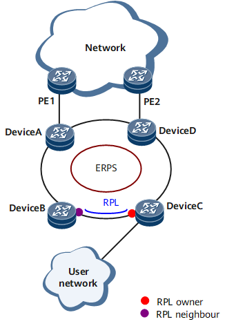
Figure 1 shows a typical ERPS single-ring network. The following describes ERPS based on this networking:
ERPS Ring
An ERPS ring consists of interconnected switches that have the same control VLAN. A ring is a basic ERPS unit.
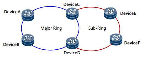
ERPS rings are classified as major rings (closed) or sub-rings (open). On the network shown in Figure 2, Device A through Device D constitute a major ring, and Device C through Device F constitute a sub-ring.
Only ERPSv2 supports sub-rings.
Node
A node refers to a switch added to an ERPS ring. A node can have a maximum of two ports added to the same ERPS ring. Device A through Device D in Figure 1 are nodes on an ERPS major ring.
Port Role
-
An RPL owner port is a ring port responsible for blocking traffic over the RPL to prevent loops. An ERPS ring has only one RPL owner port.
When the node on which the RPL owner port resides receives an R-APS PDU indicating that a link or node on the ring fails, it unblocks the RPL owner port to allow the port to send and receive traffic. This process ensures that traffic is not interrupted.
-
An RPL neighbor port is a ring port directly connected to an RPL owner port and is used to reduce the number of times that filtering database (FDB) entries are refreshed.
RPL owner and neighbor ports are both blocked under normal conditions to prevent loops.
If an ERPS ring fails, both RPL owner and neighbor ports are unblocked.
-
Ordinary ports are ring ports other than the RPL owner and neighbor ports.
An ordinary port monitors the status of the directly connected ERPS link and sends R-APS PDUs to inform the other ports if the link status changes.
Port Status
Control VLAN
A control VLAN is configured for an ERPS ring to transmit R-APS PDUs. Each ERPS ring must be configured with a control VLAN. After a port is added to an ERPS ring that has a control VLAN configured, the port is added to the control VLAN automatically. Different ERPS rings cannot be configured with the same control VLAN ID.
Unlike control VLANs, data VLANs are used to transmit data packets.
ERP Instance
On a device running ERPS, the VLAN in which R-APS PDUs and data packets are transmitted must be mapped to an Ethernet Ring Protection (ERP) instance so that ERPS forwards or blocks the VLAN packets based on blocking rules. Otherwise, VLAN packets will probably cause broadcast storms on the ring network and render the network unavailable.
Timer
-
After a faulty link or node recovers or a clear operation is executed, the nodes on the two ends of the link or the recovered node sends R-APS No Request (NR) messages to inform the other nodes of the link or node recovery and starts a guard timer. Before the timer expires, each involved node does not process any R-APS PDUs to avoid receiving out-of-date R-APS (SF) messages. After the timer expires, if the involved node still receives an R-APS (SF) message, the local port enters the Forwarding state.
-
If the RPL owner port is unblocked due to a link or node failure, the involved port may not go Up immediately after the link or node recovers. To prevent the RPL owner port from alternating between Up and Down, the node where the RPL owner port resides starts a WTR timer after receiving an R-APS (NR) message. If the node receives an R-APS Signal Fail (SF) message before the timer expires, it terminates the WTR timer (R-APS SF message: a message sent by a node to other nodes after the node in an ERPS ring detects that one of its ring ports becomes Down). If the node does not receive any R-APS (SF) message before the timer expires, it blocks the RPL owner port when the timer expires and sends an R-APS (NR, RB) message. After receiving this R-APS (NR, RB) message, the nodes set their recovered ports on the ring to the Forwarding state.
-
Protection switching sequence requirements vary for Layer 2 networks running ERPS. For example, in a multi-layer service application, a certain period of time is required for a server to recover should it fail. (During this period, no protection switching is performed, and the client does not detect the failure.) A hold-off timer can be set to ensure that the server is given adequate time to recover. If a fault occurs, the fault is not immediately reported to ERPS. Instead, the hold-off timer starts. If the fault persists after the timer expires, the fault will be reported to ERPS.
-
The WTB timer starts after an FS or MS operation is performed. When multiple nodes on an ERPS ring are in the FS or MS state, the clear operation takes effect only after the WTB timer expires. This ensures that the RPL owner port will not be blocked immediately.
The WTB timer value cannot be configured. Its value is the guard timer value plus 5.
Revertive and Non-revertive Switching
After link faults are rectified, whether to re-block the RPL owner port depends on the switching mode.
- In revertive switching, the RPL owner port is re-blocked after the wait to restore (WTR) timer expires, and the traffic channel is blocked on the RPL.
- In non-revertive switching, the traffic channel continues to use the RPL.
ERPSv1 supports only revertive switching. ERPSv2 supports both revertive and non-revertive switching.
Port Blocking Modes
ERPSv2 supports manual port blocking.
- FS: forcibly blocks a port immediately after FS is configured, irrespective of whether link failures have occurred.
- MS: forcibly blocks a port when link failures and FS conditions are absent.
- Clears an existing FS or MS operation.
- Triggers revertive switching before the WTR or wait to block (WTB) timer expires in the case of revertive operations.
- Triggers revertive switching in the case of non-revertive operations.
R-APS PDU Transmission Mode on Sub-rings
ERPSv2 supports single and multi-ring topologies. In multi-ring topologies, sub-rings have either R-APS virtual channels (VCs) or non-virtual channels (NVCs).
- With VCs: R-APS PDUs on sub-rings are transmitted to the major ring through interconnection nodes. The RPL owner port of a sub-ring blocks both R-APS PDUs and data traffic.
With NVCs: R-APS PDUs on sub-rings are terminated on the interconnection nodes. The RPL owner port blocks data traffic but not R-APS PDUs on each sub-ring.

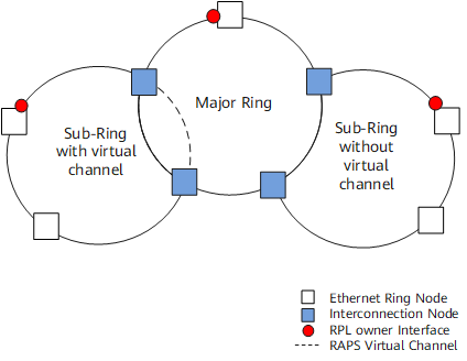
In ERPSv2, sub-rings can interlock in multi-ring topologies. The sub-rings attached to other sub-rings must use non-virtual channels.
On the network shown in Figure 3, a major ring is interconnected with two sub-rings. The sub-ring on the left has a VC, whereas the sub-ring on the right has an NVC.
By default, sub-rings use NVCs to transmit R-APS PDUs, except for the scenario shown in Figure 4.
When sub-ring links are not contiguous, VCs must be used. On the network shown in Figure 4, links b and d belong to major rings 1 and 2, respectively; links a and c belong to the sub-ring. Because links a and c are not contiguous, they cannot detect the status change between each other. Therefore, VCs must be used for R-APS PDU transmission.
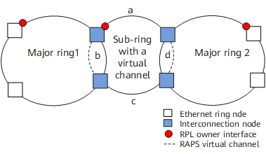
Table 2 lists the advantages and disadvantages of R-APS PDU transmission modes on sub-rings with VCs or NVCs.